Synchronizer device for a manual transmission

a synchronizer device and manual transmission technology, applied in the direction of gearing control, gearing elements, gearing, etc., can solve the problems of reducing the tip of the internal gearing to an arbitrary degree, the shifting force cannot be arbitrarily low, and the locking ring would lose its safeguarding locking effect, etc., to achieve the effect of simple manual transmission operation

Active Publication Date: 2019-07-04
GETRAG FORD TRANSMISSIONS GMBH
View PDF6 Cites 7 Cited by
  • Summary
  • Abstract
  • Description
  • Claims
  • Application Information

AI Technical Summary

Benefits of technology

[0008]One object of this the invention is to provide a synchronizer device for a manual transmission which permits a simple operation of the manual transmission.

Problems solved by technology

But the tips of the internal gearing cannot be reduced to an arbitrary degree since otherwise, the locking ring would lose its safeguarding locking effect.
In other words, the shifting force cannot be made arbitrarily low by making the tips sharper.
The shifting force exerted by the driver of the motor vehicle is limited or should, for comfort reasons, be as low as possible.
Quickly synchronizing components with high inertias, however, requires high frictional torques and thus high shifting forces.

Method used


Image

  • Synchronizer device for a manual transmission
  • Synchronizer device for a manual transmission
  • Synchronizer device for a manual transmission

Examples


Embodiment Construction

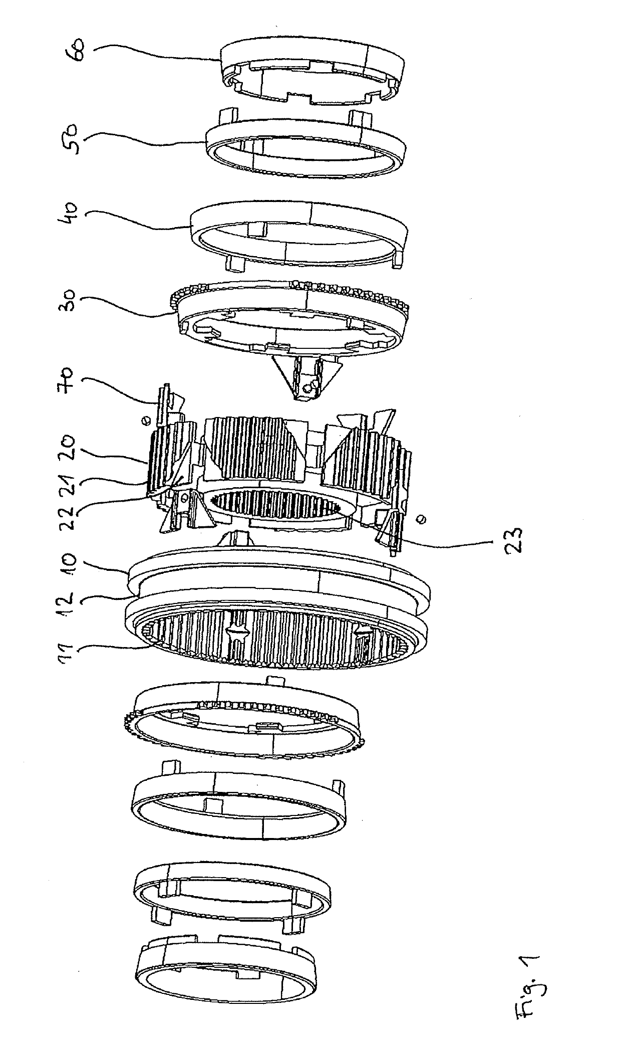
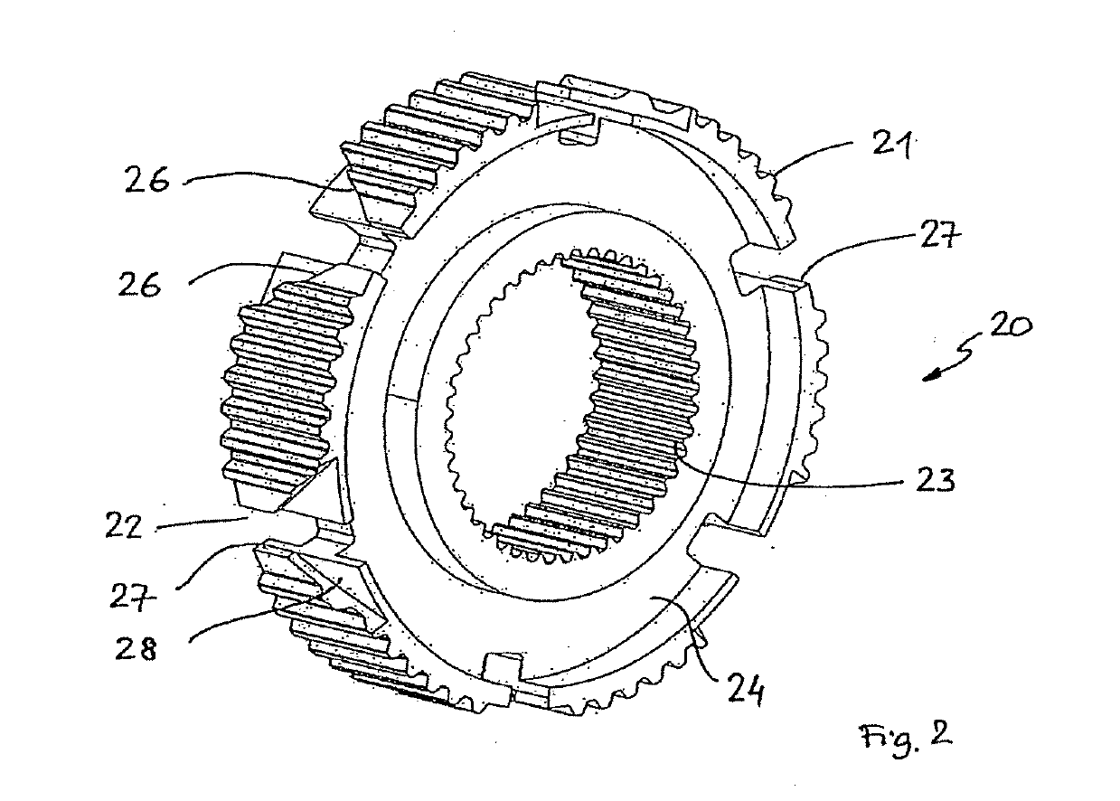
[0040]FIG. 1 shows an exploded view of an exemplary embodiment of a synchronizer device according to this invention, which is labeled in its entirety with the reference numeral 1. The synchronizer device 1 includes a slider sleeve 10, which rests against a hub 20 in the usage position. In this case, an internal gearing 11 of the slider sleeve 10 engages with an external gearing 21 of the hub 20 so that the slider sleeve 10 and the hub 20 are connected to each other in a rotationally locked fashion. The slider sleeve 10 is nevertheless able to slide back and forth in the axial direction on the hub 20.

[0041]The synchronizer device 1 also includes a locking ring 30, which is able to rotate relative to the hub 20 and slider sleeve 10 over a small angular range in the circumference direction. A friction package of the synchronizer device 1 includes an outer synchro ring 40, an intermediate ring 50, and an inner synchro ring 60.

[0042]The synchronizer device 1 also includes another locking...


PUM


Abstract

A synchronizer device for a manual transmission, having a shaft and a selector gear that is mounted on the shaft. The synchronizer device includes a hub, which can be connected to the shaft in a rotationally locked fashion, a slider sleeve, which is supported on the hub in a rotationally locked fashion, and can be slid in the axial direction, a locking element that is designed to limit the slidability of the slider sleeve in a locked position, a friction package, which has an outer synchro ring, an inner synchro ring, and an intermediate ring, which is positioned between the outer synchro ring and the inner synchro ring, with the outer synchro ring and inner synchro ring being able to rotate relative to each other, and a servo unit having a first servo surface on a first component and having a second servo surface on a second component, which rests against the first servo surface, and a torque between the first component and second component causes the first servo surface to slide along relative to the second servo surface, which produces an axially acting servo force on the friction package. According to this invention, the servo force is introduced into the friction package by the outer synchro ring and the outer synchro ring is able to rotate relative to the locking element.

Description

BACKGROUND OF THE INVENTIONField of the Invention[0001]This invention relates to a synchronizer device for a manual transmission having a shaft and a selector gear mounted on the shaft.Discussion of Related Art[0002]The synchronizer device in a manual transmission, for example, in a motor vehicle, ensures that the speed of the shaft is synchronized with the speed of the selector gear supported on it before this gear is connected to the shaft in a form-fitting manner, thus shifting into a new gear in the manual transmission. Normally, the synchronizer device includes a hub that can be connected to the shaft in a rotationally locked fashion and an axially slidable slider sleeve, which is supported on the hub in a rotationally locked fashion by a separate gearing. A locking element here, often embodied in the form of a locking ring with locking teeth, limits the slidability of the slider sleeve in a locked position. As long as the prerequisite for the locking of the locking element is ...

Claims


Application Information

Patent Timeline
Patent Type & Authority Applications(United States)
IPC IPC(8): F16D23/06F16D23/02F16D11/14F16H63/30
CPCF16D23/06F16D23/025F16D11/14F16H63/30F16D2023/0618F16H2063/3093F16D2011/002
Inventor BAEHR, JULIAN
Owner GETRAG FORD TRANSMISSIONS GMBH
Why Eureka
Try Eureka