Supercharge Your Innovation With Domain-Expert AI Agents!

Method for signal modulation based on pulse density modulation and apparatus therefor

a signal modulation and pulse density technology, applied in pulse conversion, code conversion, analogue conversion, etc., can solve the problems of e/o converter and o/e converter, and requiring additional e/o converters and o/e converters. , to achieve the effect of reducing the bandwidth of the plurality

Active Publication Date: 2019-07-04
ELECTRONICS & TELECOMM RES INST
View PDF0 Cites 0 Cited by
  • Summary
  • Abstract
  • Description
  • Claims
  • Application Information

AI Technical Summary

Benefits of technology

The present invention provides a method and apparatus for improving the bandwidth and quality of signals transmitted through a network. This is achieved by using pulse density modulation and converting the bandwidths of multiple signals to ensure they can be transmitted through the network. The result is a better signal quality and more reliable transmission of information.

Problems solved by technology

However, the analog-based optical transmission and reception system has disadvantages including degradation in signal quality due to the nonlinearity of components and signal attenuation according to transmission distance.
However, in the digital-based signal transmission structure, since a sampling frequency of the output signal of the pulse density modulator is greater than a bandwidth of the analog signal being input, there is a disadvantage in that an E / O converter and an O / E converter are additionally required.
Further, in the digital-based signal transmission structure, owing to a limitation to a transmission rate available in the E / O converter and O / E converter, there is a disadvantage in that the use of the sampling frequency of the pulse density modulator and the bandwidth of the analog signal being input for modulation are limited.
However, since the digital-based signal transmission structure to which the pulse density modulator, in which a signal output therefrom has multiple levels, is applied requires a relatively high-speed signal processing, there is a problem in that the number of levels of a signal, which can be processed by the E / O converter and the O / E converter as well as the pulse density modulator, is limited and thus an increase of a bandwidth and improvement of a signal quality are limited at a certain level.

Method used


Image

  • Method for signal modulation based on pulse density modulation and apparatus therefor
  • Method for signal modulation based on pulse density modulation and apparatus therefor
  • Method for signal modulation based on pulse density modulation and apparatus therefor

Examples


Embodiment Construction

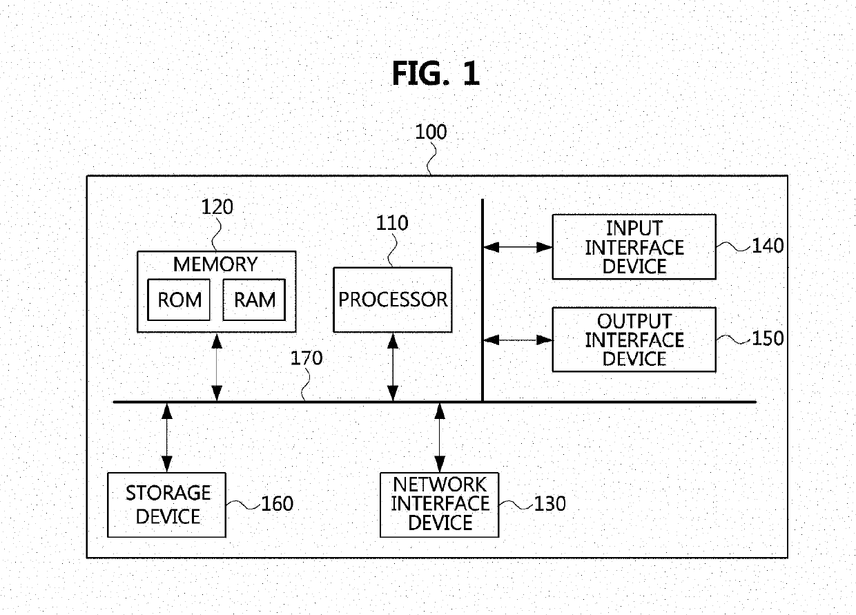
[0050]The present invention may be modified into various forms and may have a variety of embodiments, and therefore, specific embodiments will be illustrated in the drawings and described in detail. The embodiments, however, are not to be taken in a sense which limits the present invention to the specific embodiments and should be construed to include modifications, equivalents, or substitutes within the spirit and technical scope of the present invention.

[0051]Although the terms “first,”“second,” and the like may be used herein to describe various components, these components should not be limited to these terms. The terms are used only for the purpose of distinguishing one component from another component. For example, without departing from the scope of the present disclosure, a first component may be referred to as a second component, and similarly, a second component may also be referred to as a first component. The term “and / or” includes a combination of a plurality of related...


PUM


Abstract

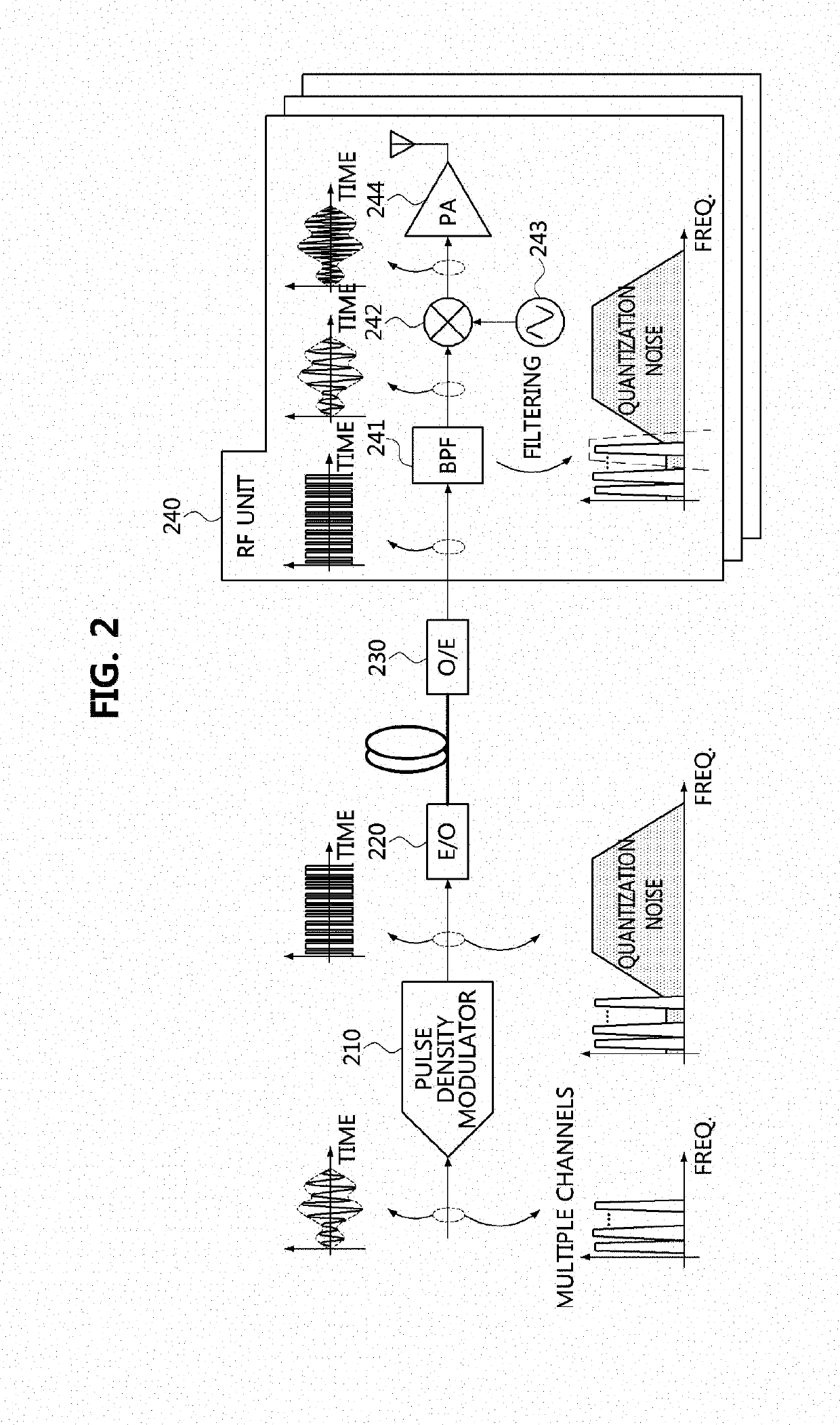
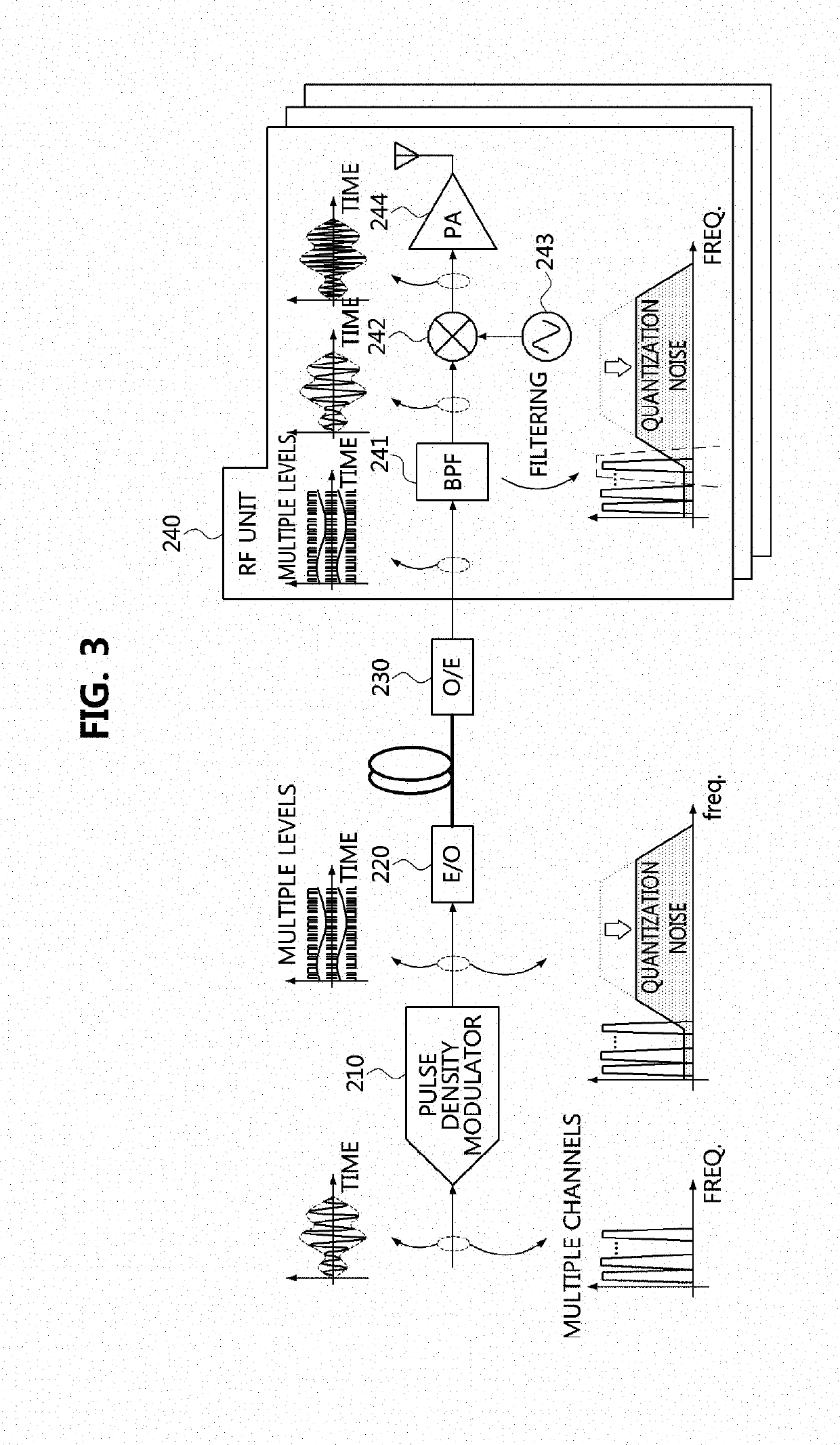
Disclosed are a method for signal modulation based on pulse density modulation and an apparatus therefore. The method for signal modulation is performed in an apparatus for modulating a signal based on pulse density modulation and includes performing pulse density modulation on an analog signal input to the apparatus through a pulse density modulator of the apparatus, converting a bandwidth of the pulse density modulated signal into a bandwidth required for the apparatus through a correlative encoder of the apparatus, transmitting the bandwidth converted signal to a radio frequency (RF) unit of the apparatus based on an electrical-to-optical (E / O) converter and an optical-to-electrical (O / E) converter of the apparatus, filtering a frequency band of the bandwidth converted signal and outputting the frequency band filtered signal via the RF unit.

Description

CROSS-REFERENCE TO RELATED APPLICATIONS[0001]This application claims priority to Korean Patent Application No. 10-2017-0182405 filed on Dec. 28, 2017 in the Korean Intellectual Property Office (KIPO), the entire contents of which are hereby incorporated by reference.BACKGROUND1. Technical Field[0002]Example embodiments of the present invention relate to a method for signal modulation based on pulse density modulation and an apparatus therefore, and more specifically, to a method for signal modulation based on pulse density modulation and an apparatus therefore so as to improve a bandwidth through which a signal is transmitted and quality of the transmitted signal.2. Related Art[0003]Recently, as traffic for wired data and wireless data is increased, a high transmission capacity is required in a transmission system for transmitting signals. In this regard, structures of various transmission systems have been studied in order to satisfy requirements for the high transmission capacity ...

Claims


Application Information

Patent Timeline
IPC IPC(8): H04L25/49H04B10/508H03M3/00
CPCH04L25/4902H04B10/508H03M3/43H04B10/2575H04B10/524H03K7/08H03M5/04H04B14/06
Inventor JANG, SEUNG HYUNKONG, SUN WOOKIM, KWANG SEONKIM, MYUNG DONLEE, HUI DONG
Owner ELECTRONICS & TELECOMM RES INST
Features
  • R&D
  • Intellectual Property
  • Life Sciences
  • Materials
  • Tech Scout
  • Unparalleled Data Quality
  • Higher Quality Content
  • 60% Fewer Hallucinations
Learn More