Yaw moment supplement for directional control

a directional control and yaw moment technology, applied in the direction of transportation and packaging, power plant types, efficient propulsion technologies, etc., can solve the problems of increasing cost, weight and complexity of aircraft, reducing the control of aircraft, etc., and achieve the effect of not decreasing the rotational speed of the rotor hub

Active Publication Date: 2019-07-11
SIKORSKY AIRCRAFT CORP
View PDF0 Cites 18 Cited by
  • Summary
  • Abstract
  • Description
  • Claims
  • Application Information

AI Technical Summary

Benefits of technology

[0014]According to another embodiment, a method of operating an aircraft includes rotating a rotor system of the aircraft about an axis of rotation, applying power, via a control unit, to

Problems solved by technology

When the rotor is in an autorotative state, however, an up-flow of air is provided to the rotor, and the ability to generate torque, and therefore yawing moment

Method used


Image

  • Yaw moment supplement for directional control
  • Yaw moment supplement for directional control
  • Yaw moment supplement for directional control

Examples


Embodiment Construction

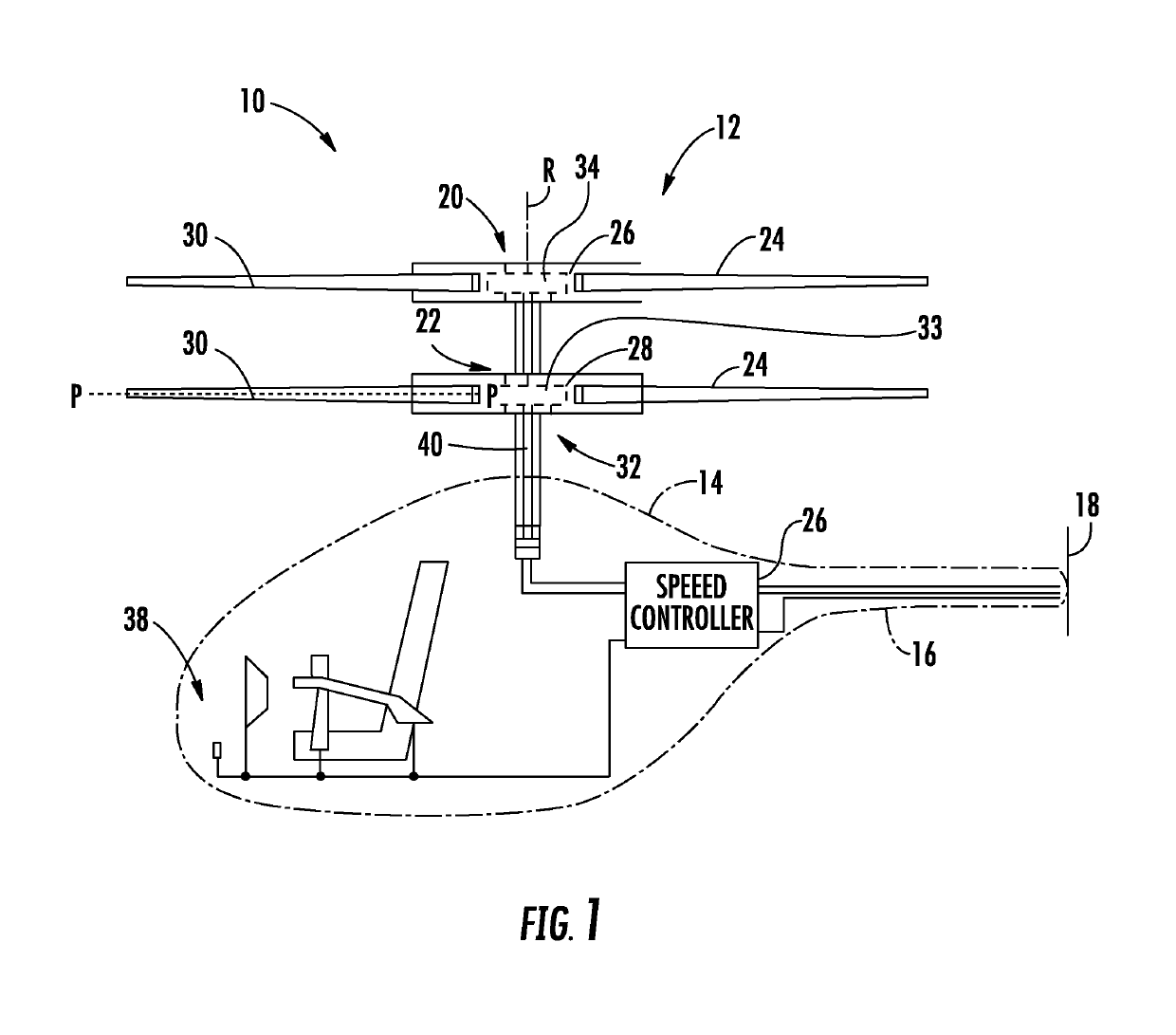
[0035]FIG. 1 schematically illustrates an example of a vertical takeoff and landing (VTOL) rotary wing aircraft 10. The aircraft 10 in the non-limiting embodiment of FIG. 1 includes a dual, counter-rotating main rotor system 12, rotatable about an axis of rotation R, supported by an airframe 14 having an extending tail 16 which mounts a thrusting device system 18, such as an auxiliary propulsion system. The dual, counter-rotating, coaxial rotor system 12 includes an upper rotor system 20 and a lower rotor system 22. Each rotor system 20, 22 includes a plurality of rotor blade assemblies 24 mounted to a rotor hub assembly 26, 28 for rotation about the rotor axis of rotation R.

[0036]The plurality of main rotor blade assemblies 24 project substantially radially outward from the hub assemblies 26, 28. Any number of main rotor blade assemblies 24 may be used with the rotor system 12. Each rotor blade assembly 24 of the rotor system 12 includes a rotor blade 30 mounted to a corresponding ...


PUM


Abstract

A rotor system of an aircraft includes a rotor hub rotatable about an axis of rotation, and a power generation system. The power generation system includes a generator stator and a generator rotor. The generator rotor is coupled to the rotor hub. At least one induction type magnet is mounted to at least one of the generator stator and the generator rotor. A control unit is operably coupled to the at least one induction type magnet to selectively deliver power to the at least one induction type magnet to alter a torque of the rotor hub without decreasing a rotational speed of the rotor hub.

Description

BACKGROUND[0001]The present disclosure relates to a rotary wing aircraft, and more particularly, to a rotary wing aircraft having a direct drive electric propulsion system.[0002]Rotor blades of rotary-wing aircraft, such as co-axial rotor helicopters, typically create lift from a down-flow of air from above. During normal powered flight operations differential collective is used to provide a yawing moment in an expected direction. When the rotor is in an autorotative state, however, an up-flow of air is provided to the rotor, and the ability to generate torque, and therefore yawing moment by differential collective, and control of the aircraft is degraded. As a result, additional means of yaw control are typically provided in such aircraft. These means may include thrusters and / or a large rudder located at the back end of the helicopters. These additional means of yaw control increase cost, weight and complexity of the aircraft.BRIEF DESCRIPTION[0003]According to an embodiment, a ro...

Claims


Application Information

Patent Timeline
IPC IPC(8): B64C27/14B64C27/32B64C27/10B64D35/02H02K7/14
CPCB64C27/14B64C27/32B64C27/10B64D35/02H02K7/14H02K21/24H02K7/10H02K11/0094H02K16/04B64D27/24B64C27/82B64D31/06Y02T50/60B64U10/14B64U10/16B64U50/19
Inventor LAUDER, TIMOTHY F.
Owner SIKORSKY AIRCRAFT CORP
Why Eureka
Try Eureka