
Thin metal film assembly and manufacturing method of the same

a technology of thin metal film and manufacturing method, which is applied in the direction of sustainable manufacturing/processing, coatings, final product manufacturing, etc., can solve the problems of undesired bending, folding, or stretching of transparent electrodes and opaque electrodes, and achieve the effect of low cost and high efficiency

Inactive Publication Date: 2019-07-25
SAMSUNG DISPLAY CO LTD
View PDF0 Cites 0 Cited by
  • Summary
  • Abstract
  • Description
  • Claims
  • Application Information

AI Technical Summary

Benefits of technology

This patent provides a way to make a thin layer of metal that is stable even when it is bent, folded, or stretched. The method is cost-effective and efficient. This invention allows for the creation of flexible thin metal layers that can be used in a variety of applications.

Problems solved by technology

Such a transparent electrode and opaque electrode may be relatively weak in terms of undesired bending, folding, or stretching.

Method used


Image

  • Thin metal film assembly and manufacturing method of the same
  • Thin metal film assembly and manufacturing method of the same
  • Thin metal film assembly and manufacturing method of the same

Examples


Embodiment Construction

[0033]Exemplary embodiments of the present invention will be described below in more detail with reference to the accompanying drawings. In this regard, the exemplary embodiments may have different forms and should not be construed as being limited to the exemplary embodiments of the present invention described herein.

[0034]Like reference numerals may refer to like elements throughout the specification and drawings.

[0035]Sizes of elements in the drawings may be exaggerated for clarity of description.

[0036]It will be understood that when a component, such as a layer, a film, a region, or a plate, is referred to as being “on” another component, the component may be directly on the other component or intervening components may be present.

[0037]As used herein, the phrase “on a plane” or “in a plan view” may refer to viewing a target portion from the top, and the phrase “on a cross-section” may refer to viewing a cross-section formed by vertically cutting a target portion from the side.

[...


PUM

PropertyMeasurementUnit
Lengthaaaaaaaaaa
Flexibilityaaaaaaaaaa
Adhesivityaaaaaaaaaa

Abstract

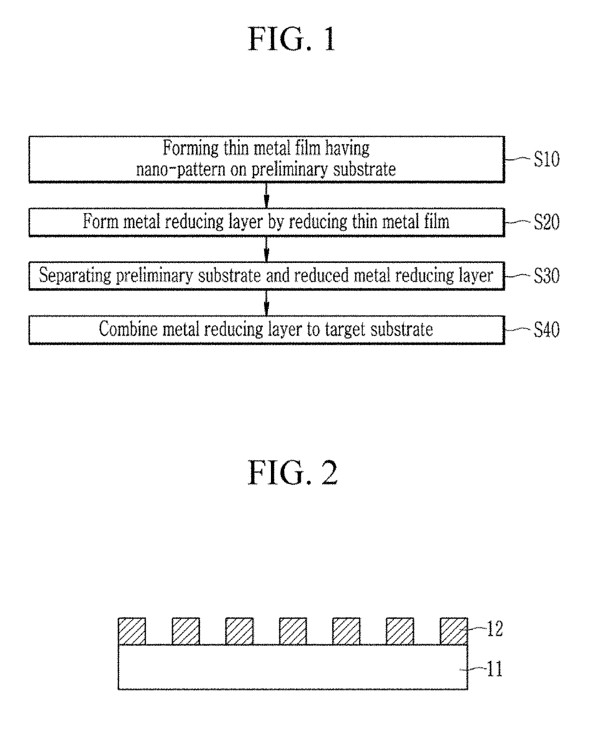
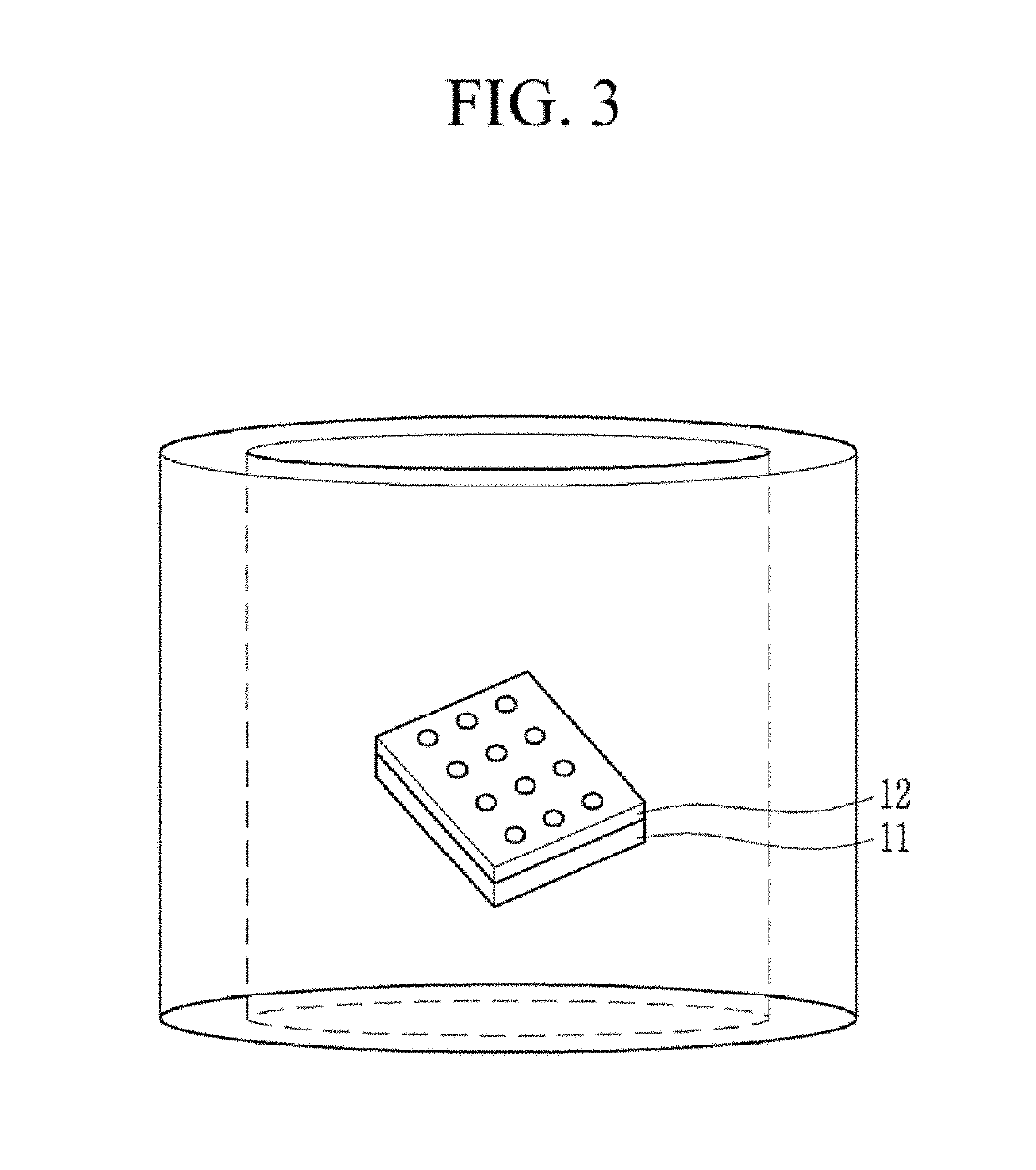
A method for manufacturing a thin metal layer assembly includes forming a thin metal layer including nanopatterns on a preliminary substrate. The method includes forming a metal reducing layer by chemically reducing the thin metal layer. The method includes separating the metal reducing layer from the preliminary substrate. The method includes bonding the metal reducing layer to a target substrate.

Description

CROSS-REFERENCE TO RELATED APPLICATION[0001]This application claims priority to Korean Patent Application No. 10-2018-0007173 filed in the Korean Intellectual Property Office on Jan. 19, 2018, the disclosure of which is incorporated by reference herein in its entirety.(a) Technical Field[0002]Exemplary embodiments of the present invention relate to a thin metal layer assembly, and more particularly to a method for manufacturing the same.(b) Discussion of Related Art[0003]A device such as a liquid crystal display (LCD), a touch panel, an electroluminescent device, or a thin film photovoltaic cell may include a plurality of electrodes or wires.[0004]As a general transparent electrode, a metal oxide such as an indium doped tin oxide (ITO) may be used, and as an opaque electrode, a thin film made of silver, copper, gold, or a combination thereof may be used.[0005]Such a transparent electrode and opaque electrode may be relatively weak in terms of undesired bending, folding, or stretchin...

Claims


Application Information

Patent Timeline
IPC IPC(8): C23C16/06C23C16/56B05D7/24
CPCC23C16/06C23C16/56B05D7/24B82Y30/00B82B1/005B82B3/008B82Y40/00H01L31/022425H01L27/124Y02E10/549Y02P70/50H10K30/81H01L21/02175H01L21/161H01L21/0274H01L21/76868H01L21/022H01L21/02244
Inventor AHN, JAE HOSHIN, JAE MINKIM, MIN WOOPARK, WON SANGKIM, SANG WOOLEE, JUNG YONG
Owner SAMSUNG DISPLAY CO LTD
Learn More