

Piezoelectric power apparatus
- Summary
- Abstract
- Description
- Claims
- Application Information
AI Technical Summary
Benefits of technology
Problems solved by technology
Method used
Image

Examples
first preferred embodiment
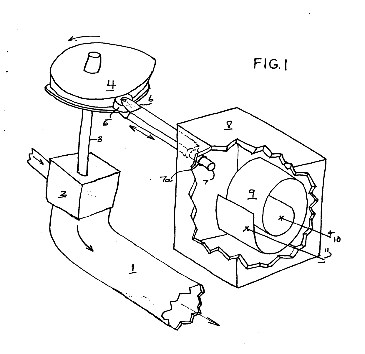
[0009]Turning to FIG. 1 we see a turbine 2 is operatively connected to fluid in fluid pipe 1. A cam 4 is in turn operatively connected to turbine 2 through the agency of shaft 3. Bracket 6 holds wheel 5 in place and is fixedly attached to piston 7. Wheel 5 is located so its outer rim is operatively connected to the outer rim of cam 4. O-ring 7a is located circumferentially around piston 7 to prevent fluid within container 8 from leaking through the hole through which piston 7 is made to enter the interior of container 8 which is made to contain piezoelectric material 9. Electric leads 10,11 are led from either side of piezoelectric material (shown in the form of a sheet) 9 through a wall of container 8 and on to the grid. The liquid within container 8 may be a dielectric such as purified water. If the liquid is not a dielectric then piezoelectric material 9 must be electrically insulated from the fluid by, for example, a rubber envelope.
[0010]In operation, fluid made to flow through...
second preferred embodiment
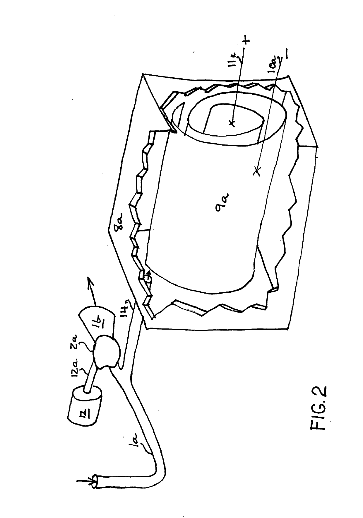
[0011]In FIG. 2 we see ball valve 2a is operatively connected to fluid made to flow through pipe 1a, 1b. Motor 12 is operatively connected to ball valve 2a through the agency of shaft 12a. Pipe 14 is made to branch off from pipe section 1a. The other end of pipe 14 is operatively connected to container 8a which is made to contain piezoelectric material 9a . Electric leads 10a, 11a are led from either side of piezoelectric material 9a through a wall of container 8a and on to the grid. The liquid within container 8a may be a dielectric such as purified water. If the liquid id not a dielectric then piezoelectric material 9a must be electrically insulated from the fluid by, for example, a rubber envelope.
[0012]In operation, pressurized fluid is made to flow intermittently through ball valve 2a as it is made to open and close by operating motor 12. As tube 14 operatively connects pipe 1a and container 8a the pressure on piezoelectric material 9a is made to vary at a rate dependent on the...
PUM
 Abstract
Description
Claims
Application Information