Laser processing method

a technology of laser processing and laser cutting, which is applied in the field of laser cutting method, can solve the problems of lowering the die strength of the device chip, hampering wiring, and lowering the quality of the cover glasses, so as to prevent the damage of the outer periphery of the device from being lowered, and the device die strength can be reduced

Inactive Publication Date: 2019-08-01
DISCO CORP
View PDF0 Cites 6 Cited by
  • Summary
  • Abstract
  • Description
  • Claims
  • Application Information

AI Technical Summary

Benefits of technology

[0006]It is therefore an object of the present invention to provide a laser processing method for forming division grooves in a workpiece by application of a laser beam to the workpiece, by which adhesion of debris to side walls of the division grooves formed can be prevented.
[0009]According to the present invention, the debris can be removed from the inside of the grooves formed by application of the laser beam, so that the debris would not remain on side walls of devices, and the die strength of the devices can be restrained from being lowered. In addition, since the protective member disposing step of disposing the protective member on the upper surface of the workpiece is conducted before the liquid layer forming step, damaging of outer peripheries of the devices can be restrained even if the laser beam is scattered by the bubbles produced.

Problems solved by technology

Then, there may arise a problem in which the debris remaining on the side walls of the device chip lowers the die strength of the device chip, or a problem in which part of the debris drops off the side walls of the device chip at the time of carrying out the device chip, possibly hampering wiring at the time of bonding the device chip onto a wiring frame.
Further, the problem in which the debris adheres to the side walls of the division grooves formed by application of the laser beam is generated also in the case where a glass plate is divided by laser beam application to produce cover glasses, thereby causing lowering in the quality of the cover glasses.

Method used


Image

  • Laser processing method
  • Laser processing method
  • Laser processing method

Examples


Embodiment Construction

[0020]A laser processing method according to an embodiment of the present invention will be described in detail below, referring to the attached drawings. The laser processing method according to the present embodiment includes: a protective member disposing step of disposing a protective member on an upper surface of a workpiece; a liquid layer forming step of forming a liquid layer on the upper surface of the workpiece; a laser beam applying step of applying a laser beam through the liquid layer to subject the upper surface of the workpiece to groove processing and to produce minute bubbles; and a debris removing step of removing debris from inside of grooves by rupture of the bubbles. The steps will be sequentially described below.

[Protective Member Disposing Step]

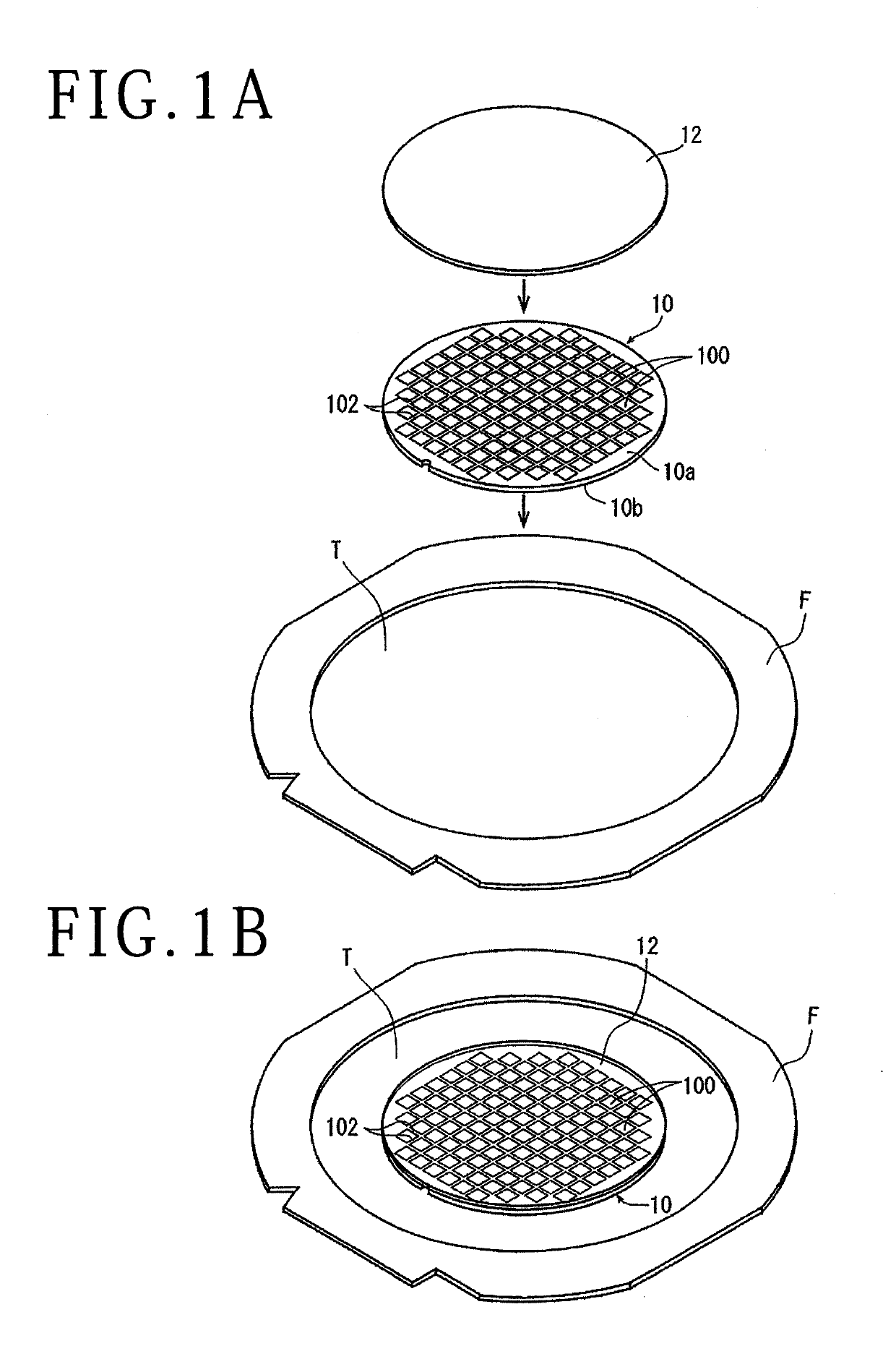
[0021]In performing the protective member disposing step in the present embodiment, first, a wafer 10 as a workpiece and a protective member 12 are prepared. As depicted in the center of FIG. 1A, the wafer 10 includes a...


PUM

PropertyMeasurementUnit
thicknessaaaaaaaaaa
widthaaaaaaaaaa
wavelengthaaaaaaaaaa

Abstract

A laser processing method for performing groove processing by applying to a workpiece a laser beam of such a wavelength as to be absorbed in the workpiece includes: a protective member disposing step of disposing a protective member on an upper surface of the workpiece; a liquid layer forming step of forming a liquid layer on the upper surface of the workpiece; a laser beam applying step of applying the laser beam through the liquid layer to subject the upper surface of the workpiece to groove processing and to produce minute bubbles; and a debris removing step of removing debris from inside of grooves by rupture of the bubbles.

Description

BACKGROUND OF THE INVENTIONField of the Invention[0001]The present invention relates to a laser processing method for processing a workpiece by applying to the workpiece a laser beam of such a wavelength as to be absorbed in the workpiece.Description of the Related Art[0002]A wafer in which a plurality of devices such as integrated circuits (ICs) and large-scale integrated circuits (LSIs) are formed on a front surface while partitioned by a plurality of intersecting division lines (streets) is divided into individual device chips by utilizing division grooves which are formed by applying to the wafer a laser beam of such a wavelength as to be absorbed in the wafer along the division lines, and the device chips are utilized in electric apparatuses such as mobile phones, personal computers and illumination apparatuses.[0003]In addition, when a laser beam of such a wavelength as to be absorbed in a wafer is applied to the wafer, so-called debris is generated and adheres to the upper su...

Claims


Application Information

Patent Timeline
Patent Type & Authority Applications(United States)
IPC IPC(8): B23K26/364B23K26/402B23K26/53B23K26/146H01L21/8258B23K26/16
CPCB23K26/364B23K26/402B23K26/53B23K26/146H01L21/8258B23K26/16B23K2101/40H01L21/687B23K26/702B23K26/0853H01L21/67092B23K26/009B23K2103/56H01L21/78H01L21/76B23K26/38
Inventor HADANO, YUJIKATAYAMA, KOICHINOMARU, KEIJI
Owner DISCO CORP
Why Eureka
Try Eureka