Method for monitoring linear dimensions of three-dimensional objects

Active Publication Date: 2019-08-01
ARTEC EURO S A R L
View PDF70 Cites 2 Cited by
  • Summary
  • Abstract
  • Description
  • Claims
  • Application Information

AI Technical Summary

Benefits of technology

[0013]The object of this invention is therefore to create an effective and efficient method of controlling linear dimensions of three-dimensional objects, as well as to expand the range of methods for controlling linear dimensions of three-dimensional objects.
[0014]The technical result ensuring that the object is achieved consists of simplification and complete automation of the proce

Problems solved by technology

The disadvantages of the known method are a high error rate caused by the fact that when optical radiation modulated along one of the coordinates through a transparency filter with a non-varied regular structure is directed at the controlled object surface, it is impossible to foresee or take into account in advance the image distortions caused by different reflective properties of the surface and deep recesses, which cannot be identified without any prior information about the macrostructure of the controlled object surface.
The limitation of the previously used method and the devices using it is poor accuracy related to the impossibility of unambiguous interpretation of the gaps in the image of the bands distorted by the contour of the controlled object surface, or by through holes, or by a low spectral reflectance value depending on the color of some area of the controlled object surface.
If the contro

Method used


Image

  • Method for monitoring linear dimensions of three-dimensional objects
  • Method for monitoring linear dimensions of three-dimensional objects
  • Method for monitoring linear dimensions of three-dimensional objects

Examples


Embodiment Construction

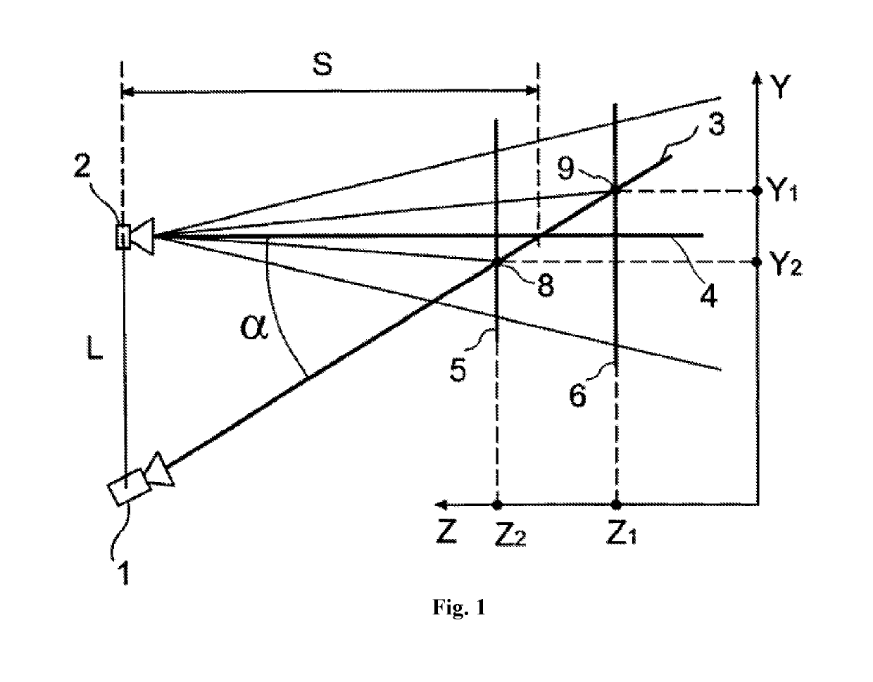
[0029]FIG. 1 shows a device comprised of projection unit 1 which projects the predetermined image onto the object and the camera 2 recording and transmitting to the computer (not shown) the light emitted by projection unit 1 and reflected from the object, at a certain triangulation angle α (angle between the central beam of the projection unit 3 and central beam 4 of camera 1.

[0030]The distance L between the camera and the projection unit is called the base. The base can be chosen as follows.

[0031]L=s*tg α, where s is the distance from the projection unit to the intersection point of the central beams of the projection unit and the camera (m).

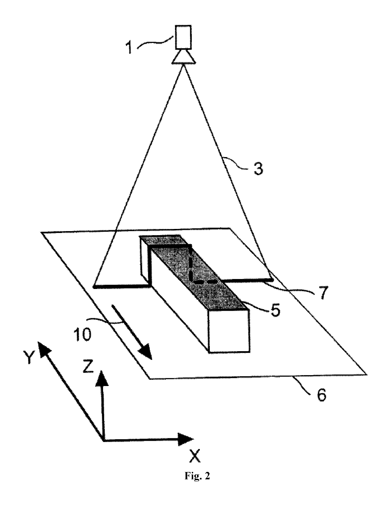
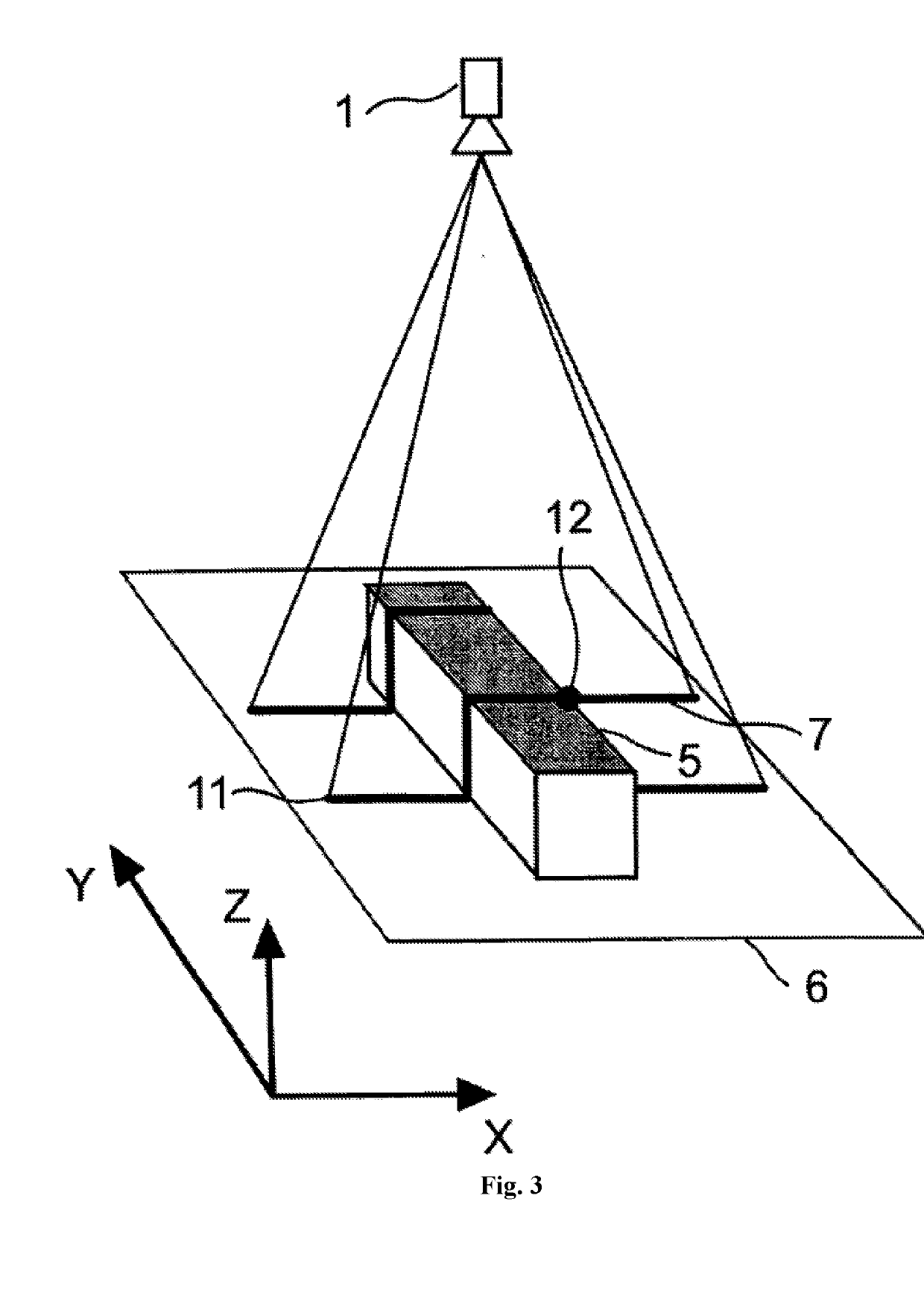
[0032]In the simplest case, projection unit 1 projects one horizontal band 3 which coincides with the central beam of the projection unit in FIG. 1. FIG. 2 is a view from camera 2. FIG. 2 shows the way band 3 is distorted due to the curvature of the object shown as planes 5 and 6, and a trace 7 of the reflected band 3 is seen in the image of ca...


PUM


Abstract

The invention relates to the field of measurement technology and relates to methods for measuring profiles of three-dimensional objects. With the aid of a projector, a previously known image which comprises non-intersecting lines is projected onto an object. The reflected signal is recorded with the aid of two cameras which are arranged at different distances away from the projector and which form different triangulation angles between the central beam of the projector and the central beams of the cameras. The distance between the projector and the closest camera is selected in such a way that the triangulation angle of the central beam of this camera and of the central beam of the projector is equal to the arctangent of the ratio of the distance between the projected bands to the depth of field of the camera lens. With the aid of the image produced by the first camera, the longitudinal and vertical coordinates of the projected lines are determined, and then the vertical coordinates of the lines are made more precise with the aid of the image produced by the second camera. The technical result consists in simplifying and expediting the measurement process.

Description

FIELD OF THE INVENTION[0001]The invention pertains to measuring instruments and can be used for 3D measurements with an adequate accuracy and display of three-dimensional object contours by observing a known projected pattern at various triangulation angles.DESCRIPTION OF THE STATE OF THE ART[0002]A previously known method for controlling linear dimensions of three-dimensional objects based on three coordinates consists of forming a probing structured backlighting on the surface of the controlled object by projecting on the surface of the controlled object a beam of light, characterized by modulated spatial intensity, registering of the image of the probing backlight pattern distorted by the topography of the controlled object's surface and determining the height of the controlled object's surface topography with a digital electronic computer measuring the topographic height based on the distortion value of the probing backlighting pattern, and calculating the other two coordinates ...

Claims


Application Information

Patent Timeline
IPC IPC(8): G01B11/00G01B11/25
CPCG01B11/002G01B11/2545G01B11/25
Inventor KLIMOV, ANDREI VLADIMIROVICHLOMAKIN, ALEKSANDR GEORGIEVICHSUKHOVEY, SERGEY VLADIMIROVICHGUSEV, GLEB ALEKSANDROVICHYUKHIN, ARTEM LEONIDOVICH
Owner ARTEC EURO S A R L
Why Eureka
Try Eureka