Restricted euclidean modulation

Active Publication Date: 2019-08-01
KYMETA
View PDF6 Cites 12 Cited by
  • Summary
  • Abstract
  • Description
  • Claims
  • Application Information

AI Technical Summary

Benefits of technology

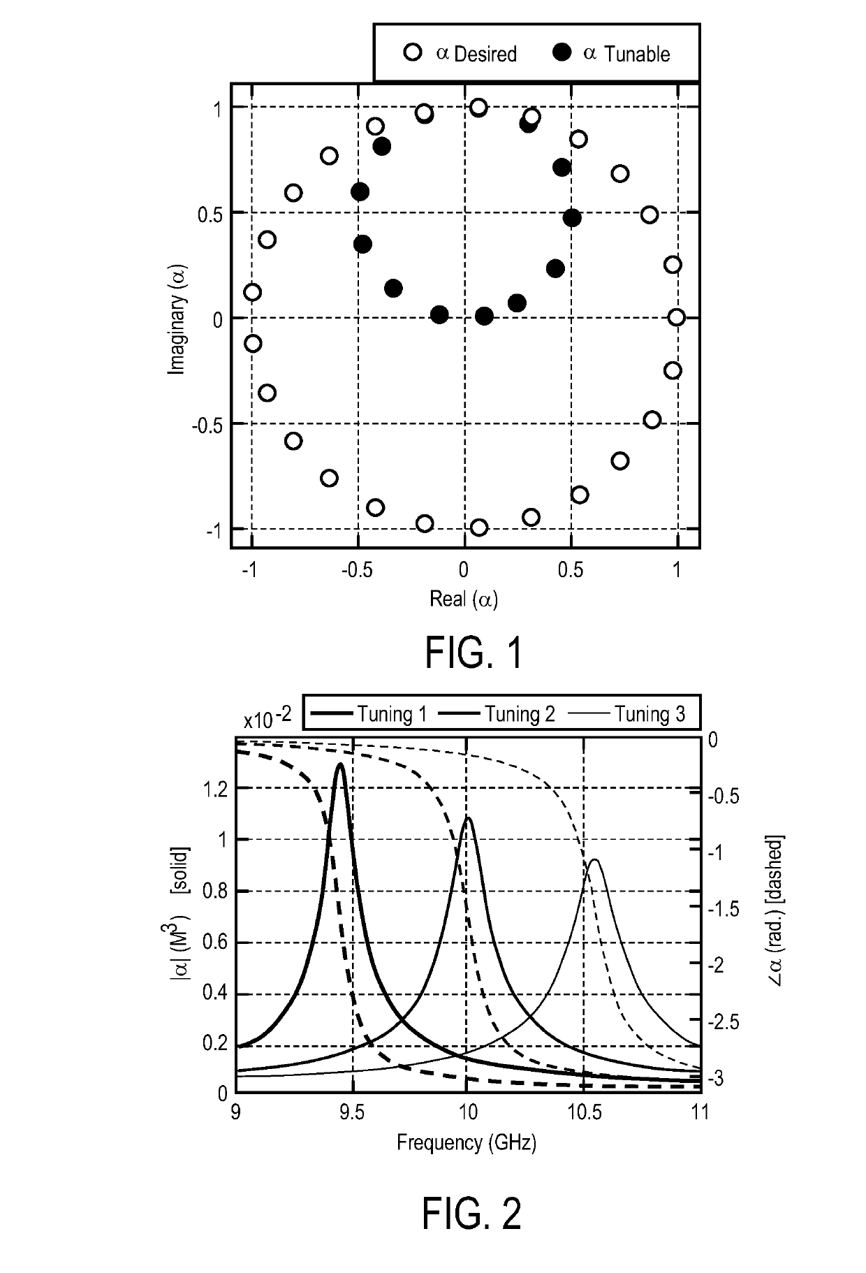
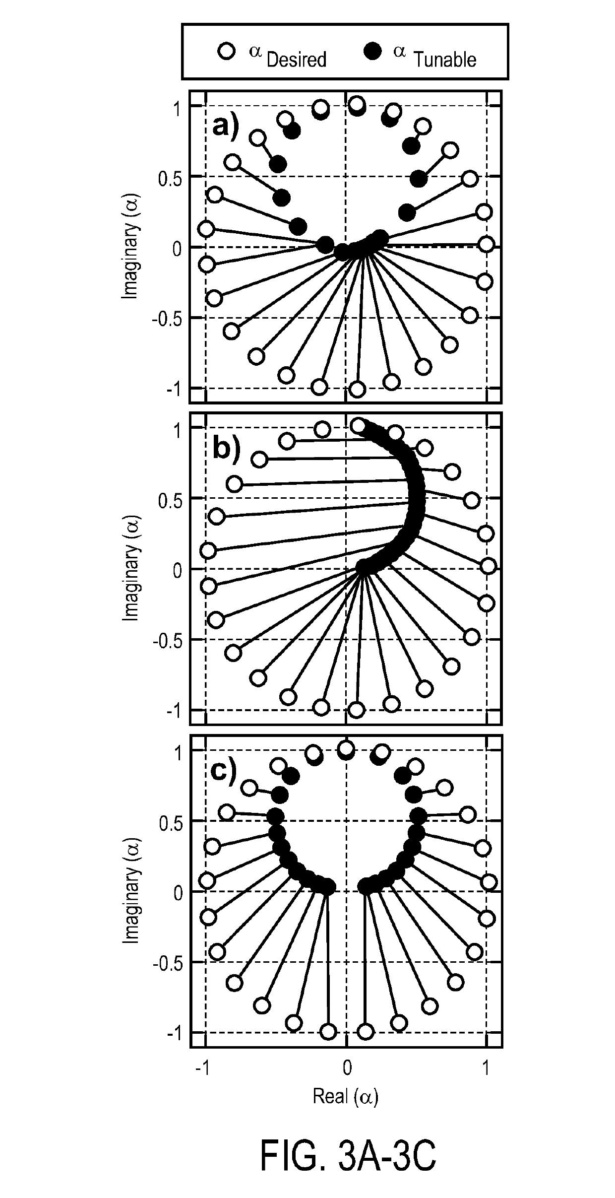
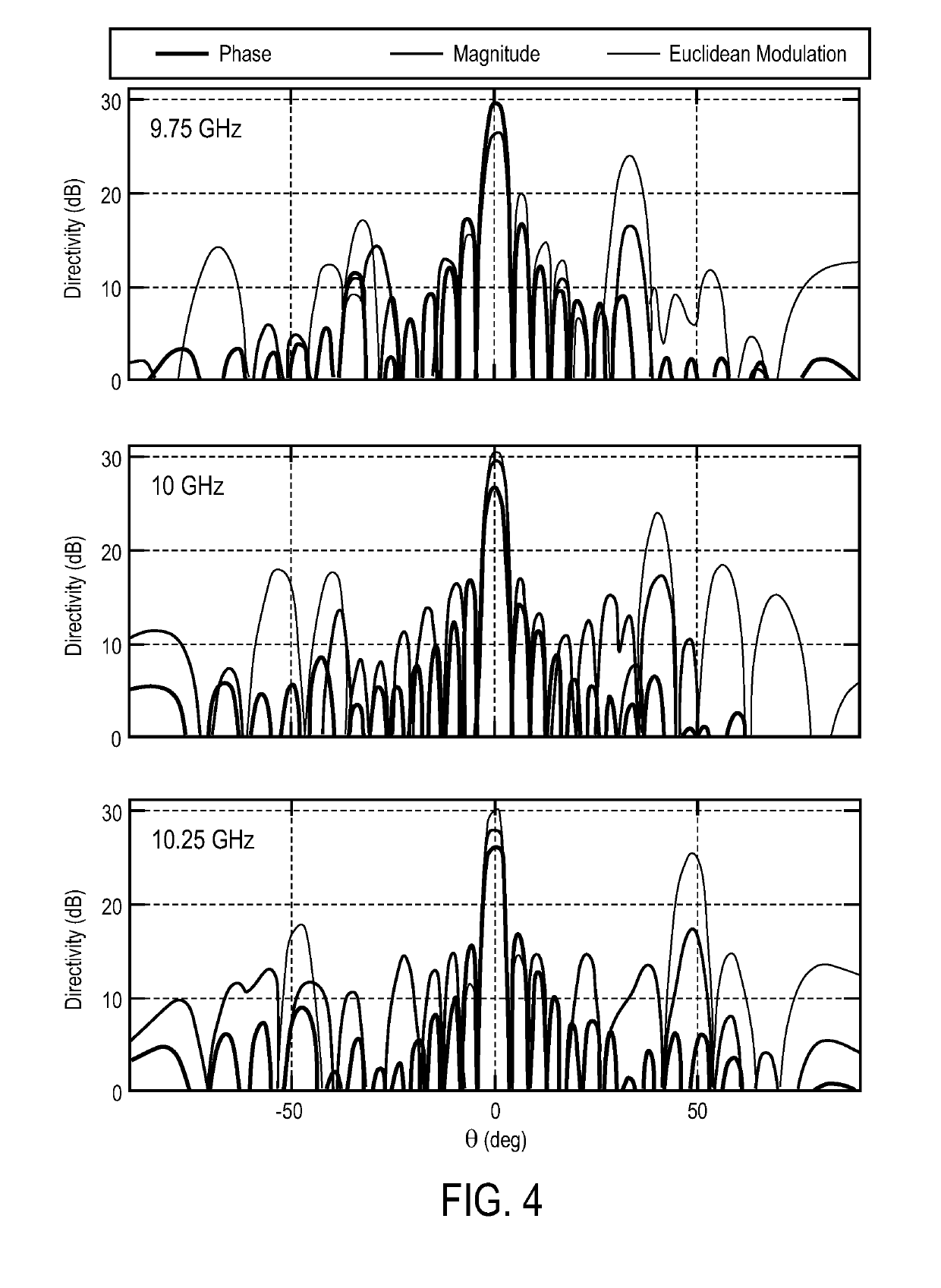
[0007]A method and apparatus for using Euclidean modulation in an antenna are disclosed. In one embodiment, a method for controlling an antenna comprises mapping a desired modulation to achievable modulation states, mapping mod

Problems solved by technology

These elements, however, do not exhibit the same level of control as is achievable with phase shifters and amplifiers, common to phased array architectures.
In further contrast to phased array antennas, however, tuning metamaterial elements does not provide independent control of both the magnitude and phase of each individual element in the

Method used


Image

  • Restricted euclidean modulation
  • Restricted euclidean modulation
  • Restricted euclidean modulation

Examples


examples of antenna embodiments

[0113]The techniques described above may be used with flat panel antennas. Embodiments of such flat panel antennas are disclosed. The flat panel antennas include one or more arrays of antenna elements on an antenna aperture. In one embodiment, the antenna elements comprise liquid crystal cells. In one embodiment, the flat panel antenna is a cylindrically fed antenna that includes matrix drive circuitry to uniquely address and drive each of the antenna elements that are not placed in rows and columns. In one embodiment, the elements are placed in rings.

[0114]In one embodiment, the antenna aperture having the one or more arrays of antenna elements is comprised of multiple segments coupled together. When coupled together, the combination of the segments form closed concentric rings of antenna elements. In one embodiment, the concentric rings are concentric with respect to the antenna feed.

Overview of an Example of Antenna Systems

[0115]In one embodiment, the flat panel antenna is part o...

an example system embodiment

[0170]In one embodiment, the combined antenna apertures are used in a television system that operates in conjunction with a set top box. For example, in the case of a dual reception antenna, satellite signals received by the antenna are provided to a set top box (e.g., a DirecTV receiver) of a television system. More specifically, the combined antenna operation is able to simultaneously receive RF signals at two different frequencies and / or polarizations. That is, one sub-array of elements is controlled to receive RF signals at one frequency and / or polarization, while another sub-array is controlled to receive signals at another, different frequency and / or polarization. These differences in frequency or polarization represent different channels being received by the television system. Similarly, the two antenna arrays can be controlled for two different beam positions to receive channels from two different locations (e.g., two different satellites) to simultaneously receive multiple...


PUM


Abstract

A method and apparatus for using Euclidean modulation in an antenna are disclosed. In one embodiment, a method for controlling an antenna comprises mapping a desired modulation to achievable modulation states, mapping modulation values associated with the achievable modulation states to one or more control parameters, and controlling radio frequency (RF) radiating antenna elements using the one or more control parameters to perform beam forming.

Description

FIELD OF THE INVENTION[0001]Embodiments of the present invention relate to the field of antennas; more particularly, embodiments of the present invention relate to the use of a distance-based mapping between desired and achievable modulation states to control a holographic beamforming antenna.BACKGROUND[0002]Metasurface antennas have recently emerged as a new technology for generating steered, directive beams from a lightweight, low-cost, and planar physical platform. Such metasurface antennas have been recently used for microwave applications and stand to provide relevant hardware and software gains for various applications such as microwave imaging, communications and synthetic aperture radar.[0003]Metasurface antennas may comprise a waveguide structure, loaded with resonant, complementary metamaterial elements in the upper surface of the waveguide that can selectively couple energy away from a guided wave into free space as radiation. By tuning the constituent elements' character...

Claims


Application Information

Patent Timeline
IPC IPC(8): H04L27/18H04B7/10H01Q13/10
CPCH04L27/18H04B7/10H01Q13/103H01Q1/38H04L27/02H04B7/0617H01Q3/44H01Q21/0012H01Q21/20
Inventor BOWEN, PATKUNDTZ, NATHAN
Owner KYMETA
Why Eureka
Try Eureka