
Control device, control method, and control program

a control device and control method technology, applied in the direction of electrical control, testing/monitoring control systems, instruments, etc., can solve the problems of high cost, cumbersome, difficult manual work to adjust control parameters such as ignition timing and air-fuel ratio, and achieve the effect of reducing the time and effort required for adjusting control parameters

Active Publication Date: 2019-08-08
HITACHI LTD
View PDF0 Cites 13 Cited by
  • Summary
  • Abstract
  • Description
  • Claims
  • Application Information

AI Technical Summary

Benefits of technology

The present invention provides a control device, method, and program that can reduce the time and effort required to adjust the control parameters necessary for power generation. This is useful for developing power generation systems that can respond to different fuel circumstances in different regions, without needing extensive manual adjustment.

Problems solved by technology

However, manual work to adjust control parameters such as an ignition timing and an air-fuel ratio is extremely difficult and cumbersome, which leads to high cost.

Method used


Image

  • Control device, control method, and control program
  • Control device, control method, and control program
  • Control device, control method, and control program

Examples


Embodiment Construction

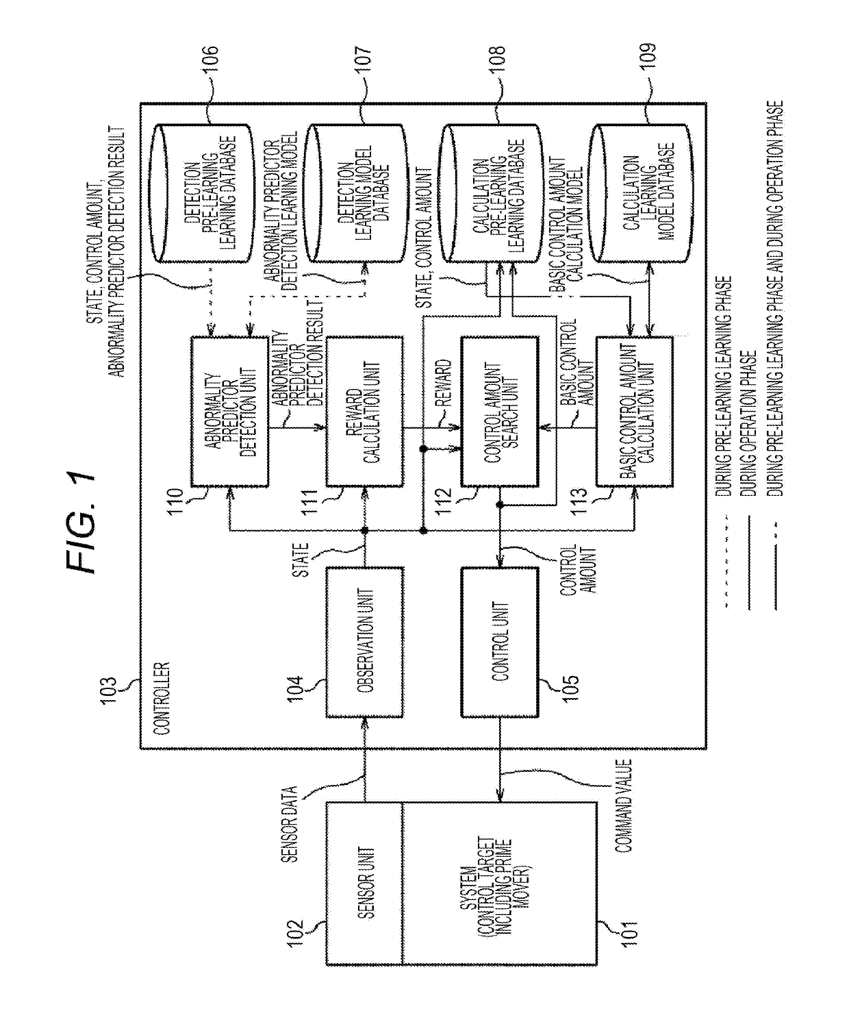
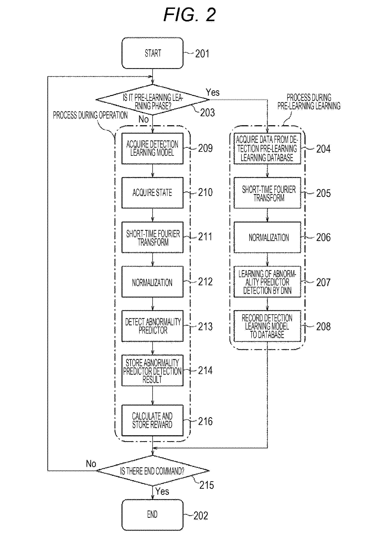
[0014]Hereinafter, modes for implementing a control device, a control method, and a control program according to the present embodiment will be described in detail with reference to the accompanying drawings. In the present embodiment, a description will be given by exemplifying an engine as a control target of the control device, but various prime movers and pumps including a motor and a turbine, or a moving object such as a vehicle, a ship, and a robot in which these motor and turbine are incorporated can be similarly applied as the control target. Hereinafter, it is considered a method of controlling an engine to improve thermal efficiency in a control system that includes a system including the engine, a sensor configured to measure a state of the system, and a controller that applies a command value to the system based on data obtained from the sensor.

[0015]FIG. 1 illustrates an overall configuration. A system 101 includes a prime mover and an object that is operated by the pri...


PUM


Abstract

The control device includes: an observation unit that calculates an amount relating to a state of a control target detected by a sensor; an abnormality predictor detection unit that detects an abnormality predictor of the control target; a reward calculation unit that calculates a reward which is an amount obtained by evaluating pass or fail of an operation of the control target; a basic control amount calculation unit that calculates data relating to the state during an operation and a basic control amount serving as a reference to control the control target; a control amount search unit that searches for a control amount at which the reward satisfies a predetermined condition based on the basic control amount, the data relating to the state during the operation and the reward; and a control unit that generates a command value to the control target.

Description

BACKGROUND OF THE INVENTION1. Field of the Invention[0001]The present invention relates to a control device, a control method, and a control program.2. Description of the Related Art[0002]Conventionally, there are various techniques of controlling a control target such as an engine using a neural network. For example, JP 2009-167968 A discloses a device that uses a neural network to calculate engine control parameters such as an engine rotation speed and an intake air pressure and controls an engine.SUMMARY OF THE INVENTION[0003]In recent years, power generation systems responding to region-specific fuel circumstances, such as gases produced in developing countries and biofuels from surplus agricultural products, have been required as a means for self-sustaining regional energy. For such a purpose, it is necessary to make a power generation engine to respond to fuel that is easily available for each region. However, manual work to adjust control parameters such as an ignition timing...

Claims


Application Information

Patent Timeline
Patent Type & Authority Applications(United States)
IPC IPC(8): F02D41/14F02D35/02G07C5/08G06N3/08
CPCF02D41/1405F02D35/024G07C5/0816G06N3/08G06F17/14F02D2041/288F02D35/023F02D35/027F02D41/2451F02D41/2477G05B23/0254G05B23/00F02D41/1404F02D41/2461F02D41/2454G06N3/088
Inventor MATSUMOTO, KOHSEIESAKI, KANAKOITO, KIYOTONAITO, HIROTOSHIRAKAWA, YUZO
Owner HITACHI LTD
Learn More