
Current modulation circuit, a driving circuit, and a method for driving a lighting load with current modulation

a current modulation and driving circuit technology, applied in the direction of electroluminescent light sources, semiconductor lamp usage, close-range type systems, etc., can solve the problems of incompatibility between the main driver's output current and local current control, the difficulty of modulating the current through the led, and waste a substantial amount of energy, so as to improve the efficiency of the system, improve the efficiency, and reduce the loss

Active Publication Date: 2019-08-08
SIGNIFY HLDG BV
View PDF10 Cites 0 Cited by
  • Summary
  • Abstract
  • Description
  • Claims
  • Application Information

AI Technical Summary

Benefits of technology

modulator circuit designed to operate at a low frequency to stabilize the current modulating element and prevent voltage drift. The circuit has two feedback control paths: one controls the voltage across the current modulating element and the other controls the data modulation. The modulator also suppresses a mains ripple that normally occurs at the output of a single stage LED driver by measuring and applying the LED current to the modulator input signal. These features improve the performance and stability of the LED driver.

Problems solved by technology

This makes it difficult to modulate the current through the LED in order to provide the desired modulated light output.
This can waste a substantial amount of energy.
There is then incompatibility between the main driver regulated output current and the local current control.
In particular, a current-regulating LED driver in series with a current-modulating transistor is known to be difficult to control.
With a minor mismatch between these two currents, clipping of the modulation current may occur or a rapid escalation of output voltage of the driver may occur that also causes dramatic power losses in the current modulator.
Such feedback loop does not compensate a possible drift in the output voltage of the driver because it only takes into account the average current.

Method used


Image

  • Current modulation circuit, a driving circuit, and a method for driving a lighting load with current modulation
  • Current modulation circuit, a driving circuit, and a method for driving a lighting load with current modulation
  • Current modulation circuit, a driving circuit, and a method for driving a lighting load with current modulation

Examples


Embodiment Construction

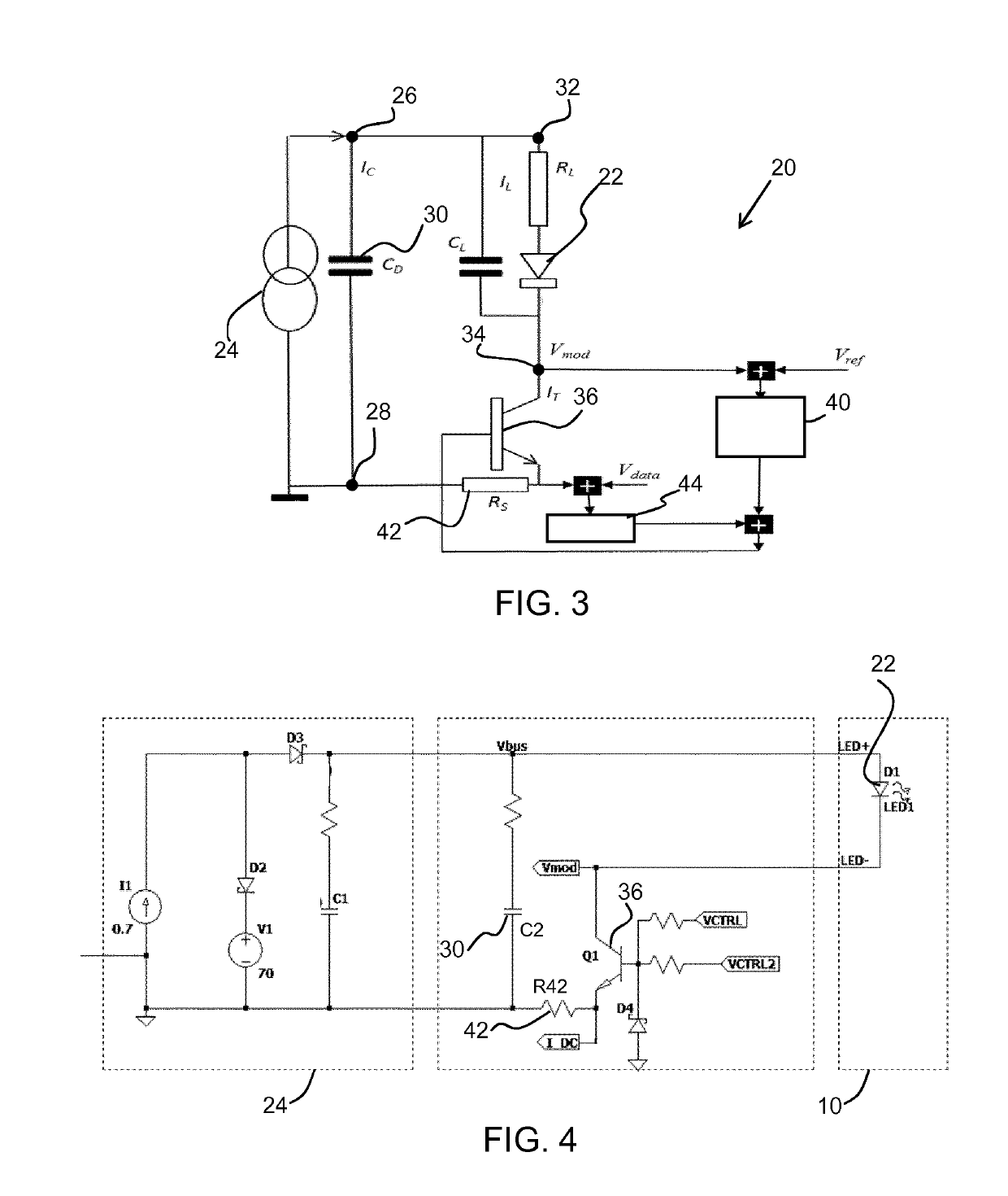
[0054]The invention provides a current modulating circuit, for example for use in a driving circuit for driving a lighting load such as an LED arrangement. A current modulating element is provided in series with the lighting load, and modulates the current based on a data input signal. A feedback system controls the current modulating element, and it has a first feedback control path which uses a voltage across the current modulating element, and a second feedback control path which uses the data input signal. The difference in current is taken up by a capacitor at the output of the driver. The voltage feedback is used to avoid a drift of the voltage across the capacitor at the output of the driver while the average current is maintained close to the current outputted by the driver.

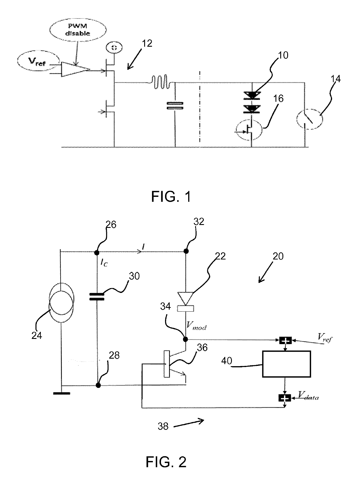
[0055]FIG. 2 shows a driving circuit 20 for driving a lighting load such as an LED load 22. The driving circuit 20 is all parts shown in FIG. 2 apart from the LED load 22.

[0056]An LED driver is shown as a...


PUM


Abstract

The invention provides a current modulating circuit, for example for use in a driving circuit for driving a lighting load such as an LED arrangement. A current modulating element is provided in series with the lighting load, and modulates the current based on a data input signal. A feedback system controls the current modulating element, and it has a first feedback control path which uses a voltage across the current modulating element, and a second feedback control path which uses the data input signal. The voltage feedback is used to maintain the overall current equal to the current output from a driver. The difference in current is taken up by a capacitor at the output of the driver.

Description

FIELD OF THE INVENTION[0001]This invention relates to the communication of data by encoding a light output.BACKGROUND OF THE INVENTION[0002]Visual light communication systems are known, in which LEDs are used to transmit data. Fast variations of the LED current are provided, which give rise to a varying light output, which conveys a data stream. The light fluctuations may be sufficiently rapid to avoid any visual light flicker. In this way, lighting components may communicate with each other or with a central system controller, for example to transmit sensor data wirelessly from a luminaire to a central controller.[0003]There is a need for a suitable circuit that can be used to modulate the LED current (or the current of any other current-drive lighting load) with data. However, a standard off-the-shelf driver delivers a constant AC current. This makes it difficult to modulate the current through the LED in order to provide the desired modulated light output.[0004]FIG. 1 shows in sc...

Claims


Application Information

Patent Timeline
Patent Type & Authority Applications(United States)
IPC IPC(8): H05B33/08H05B44/00
CPCH05B33/0812H04B10/116H05B45/395Y02B20/40H05B45/347H05B45/3725H02M1/08H02M1/14H05B47/11H05B47/185Y02B20/30
Inventor LINNARTZ, JOHAN-PAUL MARIE GERARDARULANDU, KUMARSEVO, ALEKSANDARTAO, HAIMIN
Owner SIGNIFY HLDG BV
Learn More