Oral scanner

Active Publication Date: 2019-08-15
QUISDA CORP
View PDF0 Cites 12 Cited by
  • Summary
  • Abstract
  • Description
  • Claims
  • Application Information

AI Technical Summary

Benefits of technology

[0015]In comparison to the current technology, the oral scanner disclosed in the present invention includes an outer casing, a reflector, a heat source, an optical module and a forced convection element. The outer casing has a cavity. The reflector is located at the front end of the cavity. The heat source is located in the outer casing. The optical module is located in the cas

Problems solved by technology

When the oral scanner is operated inside the oral cavity, vapor, which negatively affects the image capture quality of the oral scanner, will be ge

Method used


Image

  • Oral scanner
  • Oral scanner
  • Oral scanner

Examples


Embodiment Construction

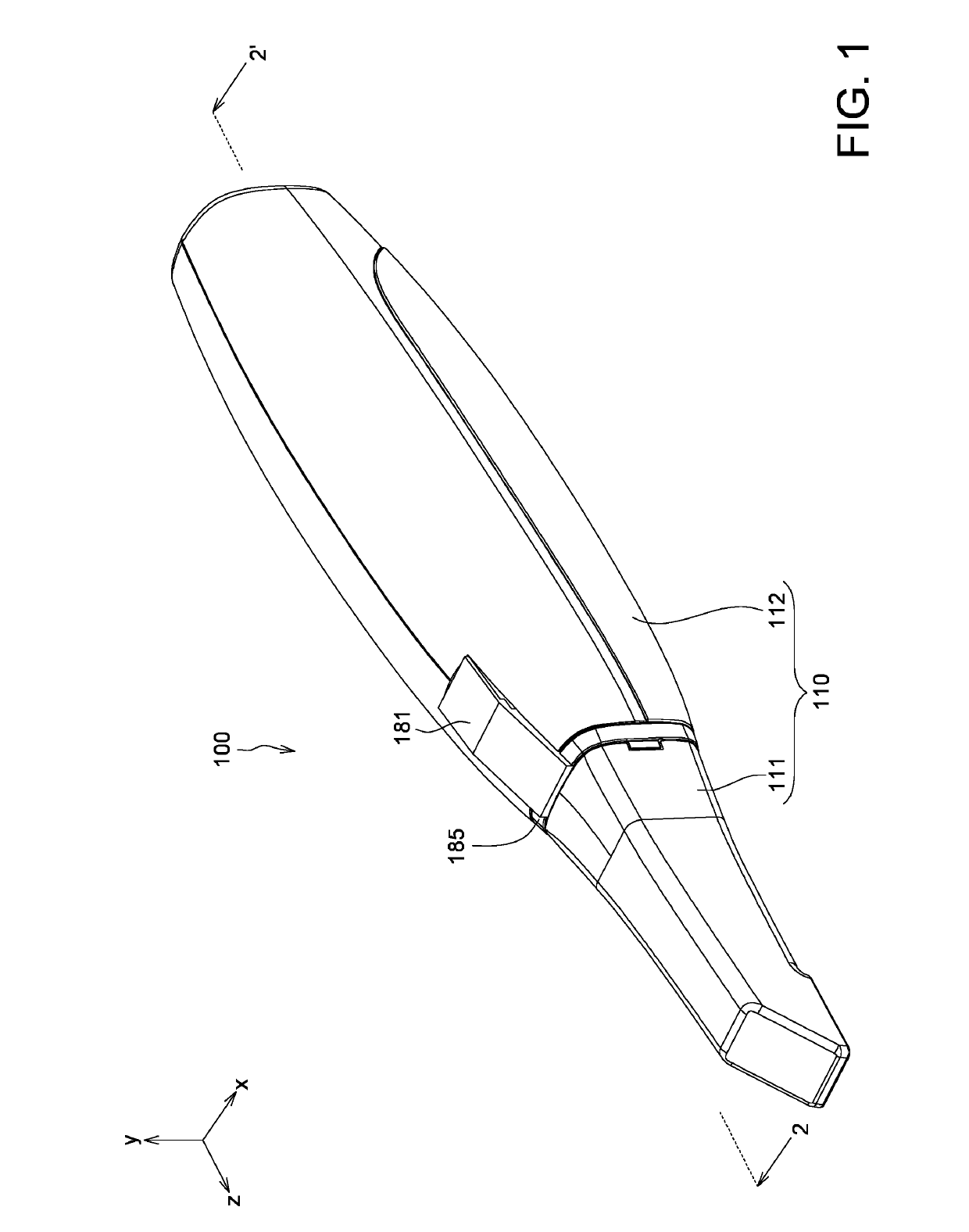
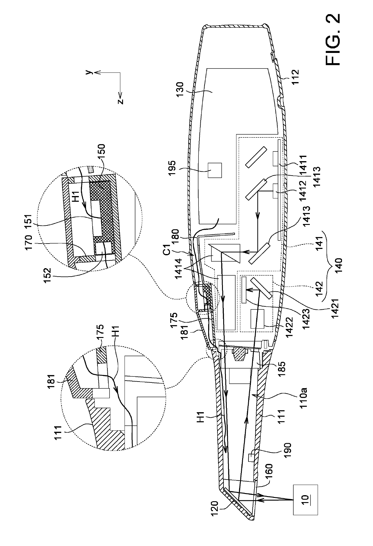
[0021]Refer to FIG. 1 and FIG. 2. FIG. 1 is a schematic diagram of an oral scanner 100 according to an embodiment of the present invention. FIG. 2 is a cross-sectional view of the oral scanner 100 of FIG. 1 along a direction 2-2′.

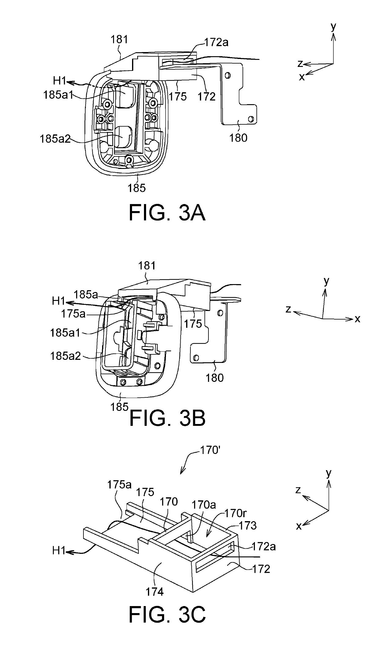
[0022]The oral scanner 100 includes an outer casing 110, a reflector 120, a heat source 130, an optical module 140, a forced convection element 150, a lens 160, a second divider 170, a carrier 175, a thermal guide 180, a first divider 185, a temperature sensor 190 and a controller 195.

[0023]The outer casing 110 has a cavity 110a. The reflector 120 is located at the front end of the cavity 110a. The heat source 130 is located in the outer casing 110. The optical module 140 is located in the outer casing 110. A heat channel C1 is formed between the optical module 140 and the outer casing 110. The forced convection element 150 is disposed in the heat channel C1 and configured to forcedly dissipate the waste heat H1 of the heat source 130 to the cavity 110a to ...


PUM


Abstract

The present invention discloses an oral scanner, including an outer casing, a reflector, a heat source, an optical module and a forced convection element. The outer casing has a cavity. The reflector is located at the front end of the cavity. The heat source is located in the outer casing. The optical module is located in the casing. A heat channel is formed between the optical module and the outer casing. The forced convection element is disposed in the heat channel and configured to forcedly dissipate the waste heat of the heat source to the cavity to heat the reflector. Thus, the temperature of the heat source can be reduced, and vapor will not be generated on the reflector heated by the waste heat.

Description

[0001]This application claims the benefit of People's Republic of China application Serial No. 201810149991.8, filed on Feb. 13, 2018, the subject matter of which is incorporated herein by reference.BACKGROUND OF THE INVENTIONField of the Invention[0002]The invention relates in general to an oral scanner, and more particularly to an oral scanner with forced convection element.Description of the Related Art[0003]When the oral scanner is operated inside the oral cavity, vapor, which negatively affects the image capture quality of the oral scanner, will be generated on the optical lens of the oral scanner if the temperature inside the oral cavity is different from the temperature inside the oral scanner. Therefore, it has become a prominent task for the industries to avoid vapor being generated on the optical lens of the oral scanner.SUMMARY OF THE INVENTION[0004]The invention is directed to an oral scanner whose forced convection element dissipates the waste heat of the heat source to...

Claims


Application Information

Patent Timeline
IPC IPC(8): A61C9/00
CPCA61C9/0053F28D2021/0029A61C19/004A61B5/0084A61B1/04A61B1/0661A61B1/253A61B5/0064A61B5/4547A61B5/4542A61B5/0088
Inventor WU, TSUNG-HSUNHSIEH, YUNG-TSUNLI, HAO-CHIEH
Owner QUISDA CORP
Why Eureka
Try Eureka