Combustor and gas turbine having the same
a gas turbine and combustor technology, applied in the direction of machines/engines, mechanical equipment, light and heating equipment, etc., can solve the problem of more stress on spot welded parts than on other parts, and achieve the effect of minimizing damage to components of the combustor and reducing stress concentration
- Summary
- Abstract
- Description
- Claims
- Application Information
AI Technical Summary
Benefits of technology
Problems solved by technology
Method used
Image

Examples
first embodiment
[0064]FIGS. 4A and 4B illustrate a coupling structure for coupling a nozzle plate 100 and an outer cap 200 of a combustor 10 according to a first embodiment of the present disclosure, with FIG. 4B showing the coupled state of FIG. 4A.
[0065]Referring to FIGS. 4A and 4B, the combustor 10 of the first embodiment includes the nozzle plate 100, the outer cap 200, first protrusions 211, and first guide holes 111.
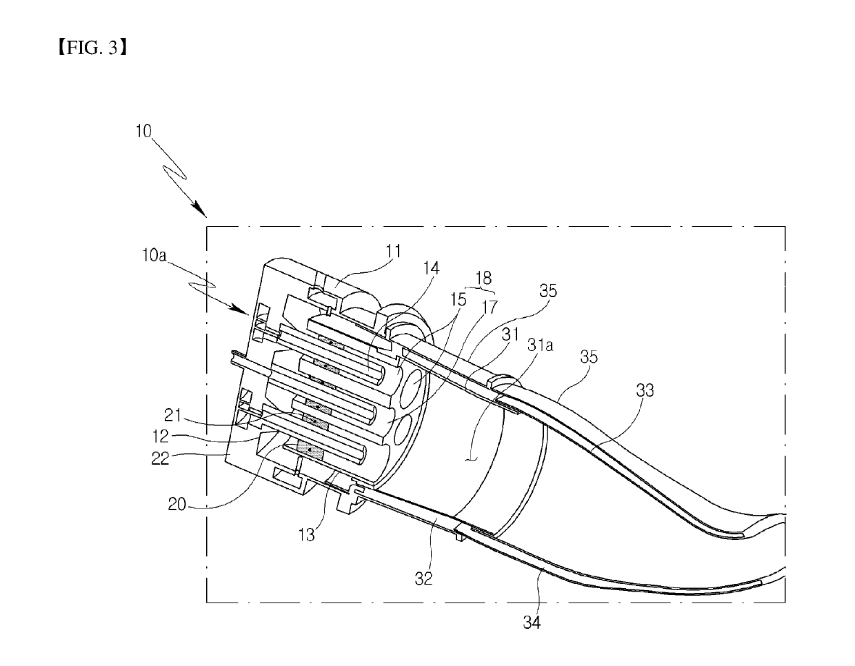
[0066]The nozzle plate 100 is a combustor component made from a heat-resistant metal and includes one end in which a plurality of nozzle fitting holes 100a are arranged to respectively receive the corresponding plurality of fuel injection nozzles 18 (FIG. 3) for injecting fuel into the combustion chamber. Thus, the nozzle plate 100 accommodates an arrangement of the fuel injection nozzles 18.
[0067]The outer cap 200 has a predetermined diameter to surround, and fit tightly with respect to, the outer circumferential surface of the nozzle plate 100. The outer cap 200 is a combustor c...
second embodiment
[0080]FIGS. 5A and 5B illustrate a coupling structure for coupling a nozzle plate 100 and an outer cap 200 of a combustor 10 according to a second embodiment of the present disclosure, with FIG. 5B showing the coupled state of FIG. 5A.
[0081]Referring to FIGS. 5A and 5B, the combustor 10 according to the second embodiment of the present disclosure includes the nozzle plate 100, the outer cap 200, second protrusions 121, and second guide holes 221.
[0082]The nozzle plate 100 is a component of the combustor 10 and is made from a heat-resistant metal. As in the first embodiment, the nozzle plate 100 accommodates a plurality of nozzle fitting holes 100a (FIG. 4A) in which fuel injection nozzles 18 (FIG. 3) are respectively received to inject fuel into the combustion chamber.
[0083]The outer cap 200 has a predetermined diameter to surround, and fit tightly with respect to, the outer circumferential surface of the nozzle plate 100. The outer cap 200 is a combustor component made from a heat-...
third embodiment
[0100]FIGS. 6A and 6B illustrate a coupling structure for coupling a nozzle plate 100 and an outer cap 200 of a combustor 10 according to a third embodiment of the present disclosure, with FIG. 6B showing the couple state of FIG. 6A.
[0101]Referring to FIGS. 6A and 6B, the combustor 10 according to the third embodiment of the present disclosure includes the nozzle plate 100, the outer cap 200, second protrusions 121, and second guide holes 231.
[0102]The nozzle plate 100 is a component of the combustor 10 and is made from a heat-resistant metal. As in the first embodiment, the nozzle plate 100 accommodates a plurality of nozzle fitting holes 100a (FIG. 4A) in which fuel injection nozzles 18 (FIG. 3) are respectively received to inject fuel into the combustion chamber.
[0103]The outer cap 200 has a predetermined diameter to surround, and fit tightly with respect to, the outer circumferential surface of the nozzle plate 100. The outer cap 200 is a combustor component made from a heat-res...
PUM
 Abstract
Description
Claims
Application Information
 - R&D
- Intellectual Property
- Life Sciences
- Materials
- Tech Scout
- Unparalleled Data Quality
- Higher Quality Content
- 60% Fewer Hallucinations
Browse by: Latest US Patents, China's latest patents, Technical Efficacy Thesaurus, Application Domain, Technology Topic, Popular Technical Reports.
© 2025 PatSnap. All rights reserved.Legal|Privacy policy|Modern Slavery Act Transparency Statement|Sitemap|About US| Contact US: help@patsnap.com