Charging system having an integrated coolant reservoir

a charging system and coolant reservoir technology, applied in the direction of electric vehicles, electrical equipment, electrical apparatus, etc., can solve the problems of obvious disadvantages on the operator and user side, and the inability to implement properly functioning air cooling, so as to prevent excessive cold and excessive hot temperatures

Active Publication Date: 2019-08-22
DR ING H C F PORSCHE AG
View PDF0 Cites 11 Cited by
  • Summary
  • Abstract
  • Description
  • Claims
  • Application Information

AI Technical Summary

Benefits of technology

[0017]According to another embodiment of the charging system, the coolant reservoir may have a capacity of an order of magnitude of around 200 liters or more per charging connector. As a result, the coolant reservoir may provide enough cooling capacity and serve as primary cooling source for the buffer storage device and the power electronics.
[0018]According to another embodiment of the charging system, the cooling system may also be operated as a heating system and, where necessary, output the energy stored in the coolant reservoir in relation to the surrounding temperature in the form of heat to components of the charging system. By way of example, the charging cable may thus be heated in winter such that it remains flexible. To this extent, the cooling system may be considered to be a temperature control system that is able to prevent excessively cold and excessively hot temperatures of the components whose temperature is able to be controlled thereby.

Problems solved by technology

In the case of the high charging currents that arise during the charging procedure, cooling of the power electronics is essential, since otherwise the power electronics may be damaged by overheating at relatively high external temperatures and in particular as the number of charging procedures increases, with consequences on the operator side and user side that are obviously disadvantageous.
Properly functioning air cooling is however only able to be implemented if the installation space for the charging column is relatively large and there is enough space for corresponding air stream guidance.

Method used


Image

  • Charging system having an integrated coolant reservoir
  • Charging system having an integrated coolant reservoir

Examples


Embodiment Construction

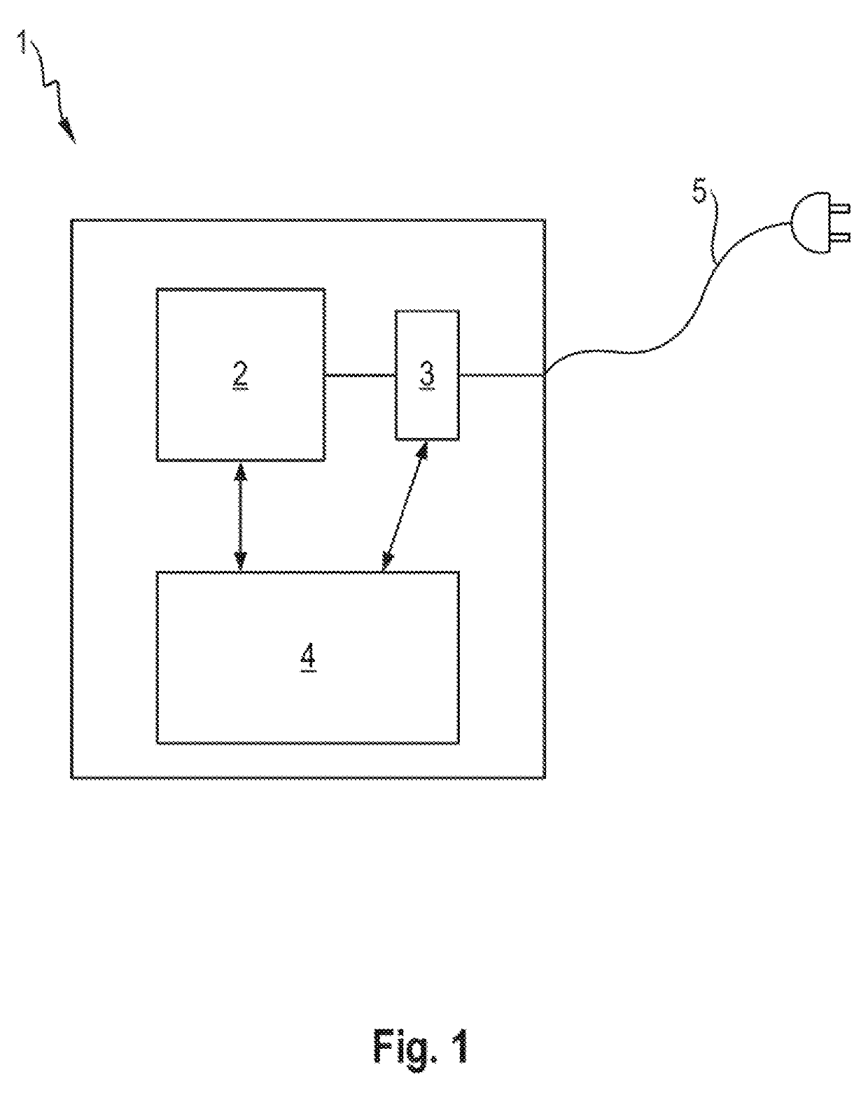
[0024]FIG. 1 shows a schematic view of a charging system 1 according to various exemplary embodiments. The charging system has a charging station 1 including a buffer storage device 2 for storing energy. Furthermore, power electronics 3 are arranged in the charging station 1, power electronics being understood to mean the combination of all of the electrical and electronic components that are involved in providing energy from the buffer storage device 2 and / or the mains connection in order to charge an electric vehicle. The charging station 1 furthermore includes power electronics 3, which use a necessary voltage conversion and possible current conversion to provide a charging current, by way of which an electric vehicle connected to the charging station 1 via a charging connector 5 is able to be charged. Although only one charging connector 5 is shown in FIG. 1, more charging connectors may obviously be provided. In addition, the at least one charging connector 5 may also be arrang...


PUM


Abstract

A charging system for charging an electric vehicle is provided. The charging system includes a charging station, at least one charging connector, which is able to be coupled to the electric vehicle in order to charge same, a buffer storage device for storing energy, power electronics that are configured to provide the energy from the buffer storage device and/or from a mains connection to the charging station at the at least one charging connector, and a coolant reservoir in which a coolant for cooling the power electronics is stored.

Description

CROSS-REFERENCE TO RELATED APPLICATION[0001]This application claims priority to German Patent Application No. DE 10 2018 103 706.6, filed Feb. 20, 2018, which is incorporated by reference herein in its entirety.FIELD OF THE INVENTION[0002]The present invention relates in general to a charging system having an integrated coolant reservoir. The charging system may be in particular a charging system incorporating an electric buffer storage device for charging electric vehicles and a reservoir for a liquid coolant.BACKGROUND OF THE INVENTION[0003]Electromobility has taken on increasing importance in recent years. To promote the proliferation of electric vehicles, it is desirable for the charging procedure for an electric vehicle to be quick, uncomplicated and possible at any time. Nowadays, modern electric vehicles are able to be charged with charging powers beyond 100 kW, with charging currents in the region of 300 amperes and more. The power electronics in the charging station transfo...

Claims


Application Information

Patent Timeline
Patent Type & Authority Applications(United States)
IPC IPC(8): B60L53/302B60L53/31B60L53/16H05K7/20
CPCB60L53/302B60L53/31B60L53/16H05K7/20927H05K7/20272B60L53/14B60L53/53Y02T10/70Y02T90/14Y02T10/7072Y02T90/12
Inventor HEYNE, RAOULJOSLOWSKI, FLORIAN
Owner DR ING H C F PORSCHE AG
Why Eureka
Try Eureka