Realtime, verified and automated demand response energy saving controller

a real-time, verified and automated technology, applied in space heating and ventilation control systems, lighting and heating apparatuses, heating types, etc., can solve problems such as inability to summariz

Inactive Publication Date: 2019-08-22
LAU JAMES LEYCH
View PDF0 Cites 5 Cited by
  • Summary
  • Abstract
  • Description
  • Claims
  • Application Information

AI Technical Summary

Benefits of technology

[0035]In another embodiment, the new MVDR can be made as part of a pool pump controller unit eliminating a separate device to be connected to the pool pump controller.
[0036]In another embodiment, the new MVDR can be made as part of a refrigeration controller unit of a refrigerator, fr...

Problems solved by technology

Moreover, this Summary is not intended for use as an ...

Method used


Image

  • Realtime, verified and automated demand response energy saving controller
  • Realtime, verified and automated demand response energy saving controller
  • Realtime, verified and automated demand response energy saving controller

Examples


Embodiment Construction

[0052]What follows is a detailed description of the preferred embodiments of the invention in which the invention may be practiced. Reference will be made to the attached drawings, and the information included in the drawings is part of this detailed description. The specific preferred embodiments of the invention, which will be described herein, are presented for exemplification purposes, and not for limitation purposes. It should be understood that structural and / or logical modifications could be made by someone of ordinary skills in the art without departing from the scope of the invention. Therefore, the scope of the invention is defined by the accompanying claims and their equivalents.

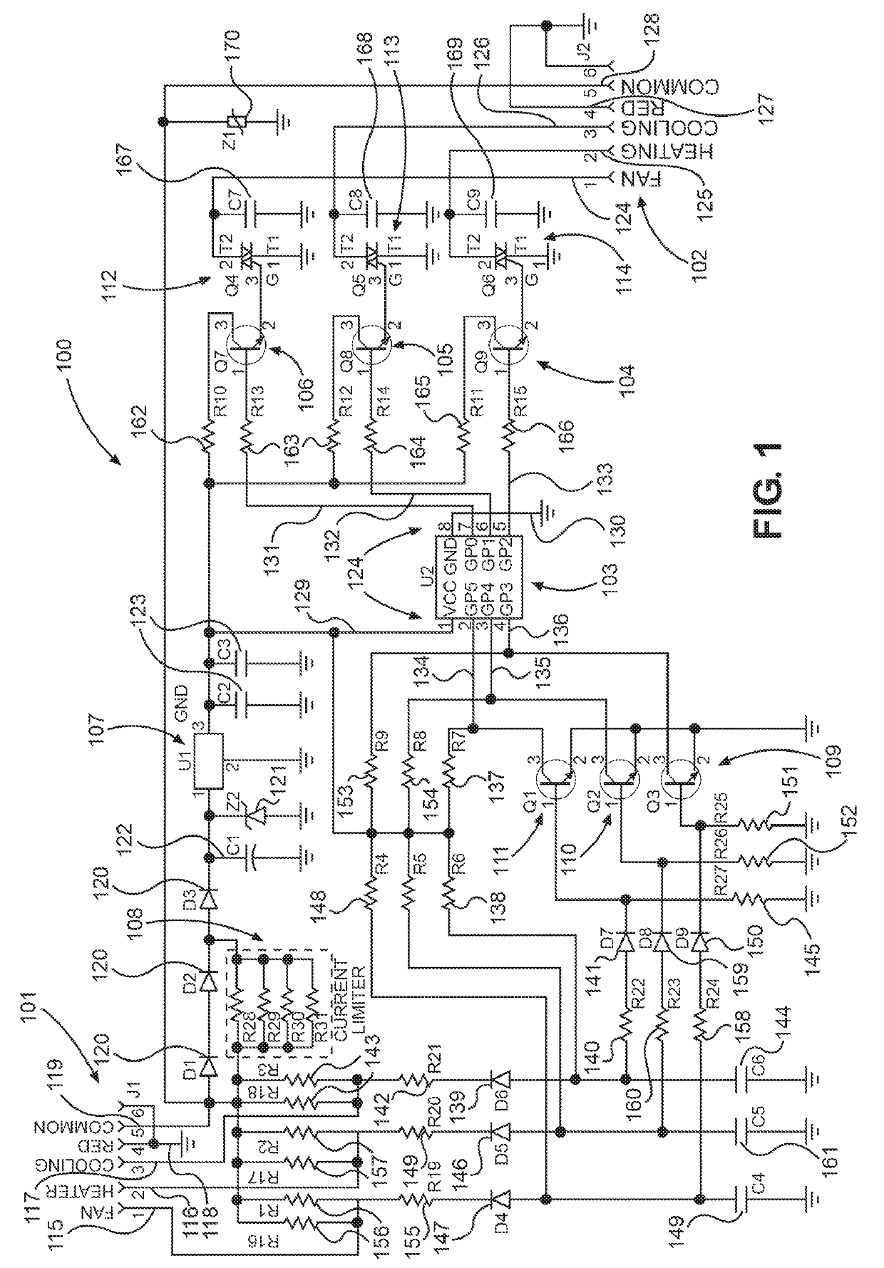
[0053]FIG. 1 illustrates a schematic circuit diagram of an integrated ESC circuit 100 for controlling the fan, the compressor and the heater of a heating, ventilation and air conditioning (HVAC) system. Preferably, the integrated circuit 100 comprises an input port 101 having a plurality of input ...


PUM


Abstract

Energy saving devices and methods for HVAC or other energy consuming systems and particularly plug and play energy saving controllers adapted to predict energy usage and savings, such as by extending the fan run time of HVAC systems after the heating or cooling unit has shut off and/or by stopping the compressor or heater for a short duration of time if the compressor or heater has been running continuously for fixed periods of time, while the fan is still blowing, wherein the energy saving controller is integrated with a wireless-enabled, real-time measurement and verification system, and with demand response capability.

Description

CROSS-REFERENCE TO RELATED APPLICATIONS[0001]This application is a continuation-in-part and claims the benefit of U.S. Non-Provisional application Ser. No. 16 / 036,796 filed Jul. 16, 2018, which is a continuation-in-part and claims the benefit of U.S. Non-Provisional application Ser. No. 15 / 787,672 filed Oct. 18, 2017 (now U.S. Pat. No. 10,174,966), which is a continuation-in-part and claims the benefit of U.S. Non-Provisional application Ser. No. 15 / 093,669 filed Apr. 7, 2016 (now U.S. Pat. No. 10,119,719) and of U.S. Non-Provisional application Ser. No. 15 / 344,483 filed Nov. 4, 2016 (now U.S. Pat. No. 10,066,849), said application Ser. No. 15 / 093,669 filed Apr. 7, 2016 being a continuation-in-part of U.S. Non-Provisional application Ser. No. 14 / 628,159, filed Feb. 20, 2015, (now U.S. Pat. No. 10,047,969) which in turn is a continuation-in-part of U.S. Non-Provisional application Ser. No. 14 / 332,714, filed Jul. 16, 2014 (now abandoned) and U.S. Non-Provisional application Ser. No. 1...

Claims


Application Information

Patent Timeline
IPC IPC(8): F24F11/46F24F11/58F24F11/77F24F11/86
CPCF24F11/46F24F11/58F24F11/77F24F11/86F24F2110/10F24F11/30F24F2130/10Y02B30/70
Inventor LAU, JAMES LEYCH
Owner LAU JAMES LEYCH
Why Eureka
Try Eureka