
Method and apparatus to minimize the effects of radar anomalous propagation for air traffic control

a radar anomalous and propagation technology, applied in the field of anomalous propagation (ap), can solve the problems of false weather reports, radar systems newer than, false returns, etc., and achieve the effects of extending the clutter map, increasing the sensitivity of the receiver, and increasing the volume of receive beam sampling

Inactive Publication Date: 2019-08-22
INTERSOFT ELECTRONICS INC
View PDF0 Cites 0 Cited by
  • Summary
  • Abstract
  • Description
  • Claims
  • Application Information

AI Technical Summary

Benefits of technology

The patent text describes a method to improve the performance of existing radar terminals by using a more efficient radar transmitter and receiver. This results in a 6 to 10 dB improvement in the range of the terminals, allowing for better detection and classification of target Kennan describes a method that improves the ability of radar to detect and classify objects. This is accomplished by using a special speed sensor and a more powerful laser to increase the sensitivity of the radar system. This makes it possible to detect smaller objects and to better distinguish them from other objects. Overall, this method helps to improve the performance of existing radar systems and allows for better detection and classification of target objects.

Problems solved by technology

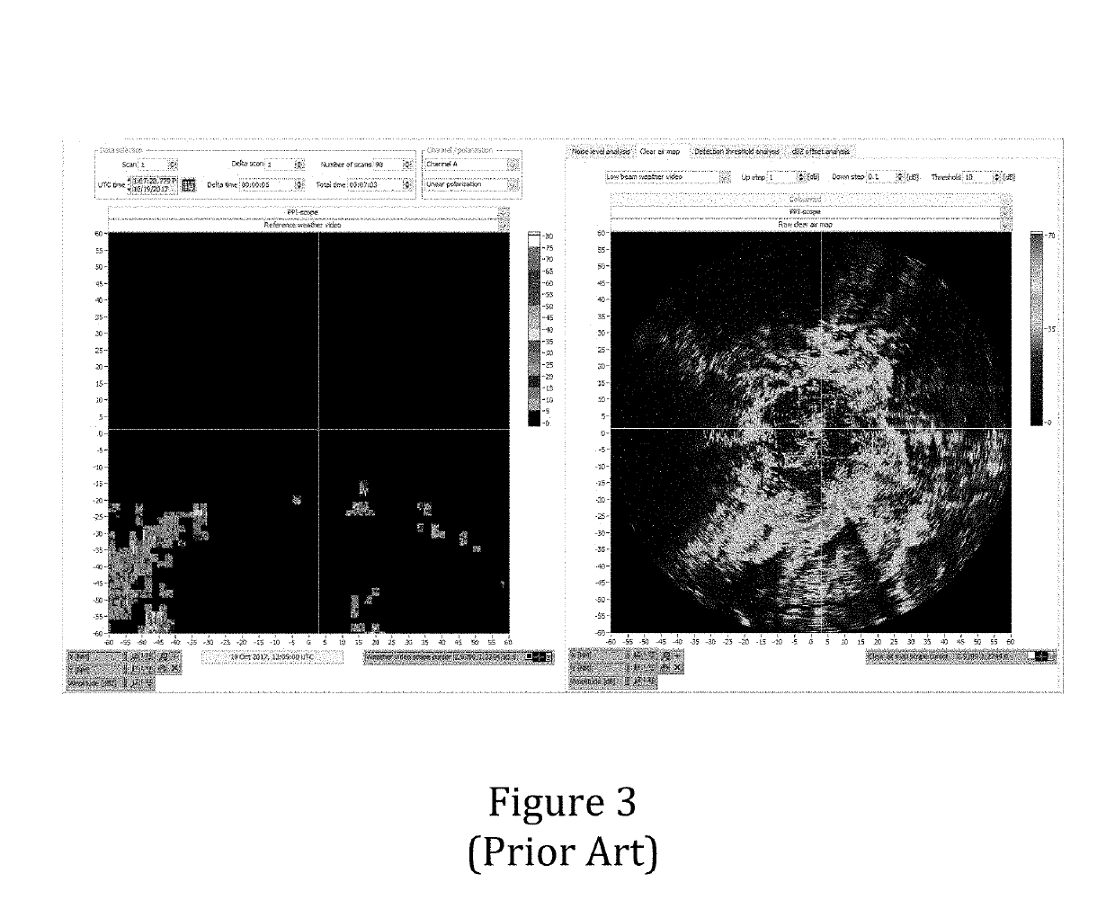
Under certain conditions the radar beam can become trapped in the atmosphere, in an abnormality known as ducting, producing false returns from the ground.
All terminal radar systems are subject to the effects of anomalous propagation: a phenomenon that can cause beam bending and erroneous clutter returns, leading to false weather reports.
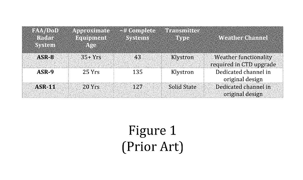
All three of these systems have experienced false weather issues over the years resulting from anomalous propagation.
However, even with a separate weather channel and specialized weather processing functions, extensive ASR-9 deployment in the 1990s highlighted many issues with AP causing ground clutter breakthrough (Weber et al., 1991, incorporated herein by reference).
Therefore, even with separate weather channels and various design processing features, radar systems newer than the ASR-8 continued to suffer from the effects of AP.
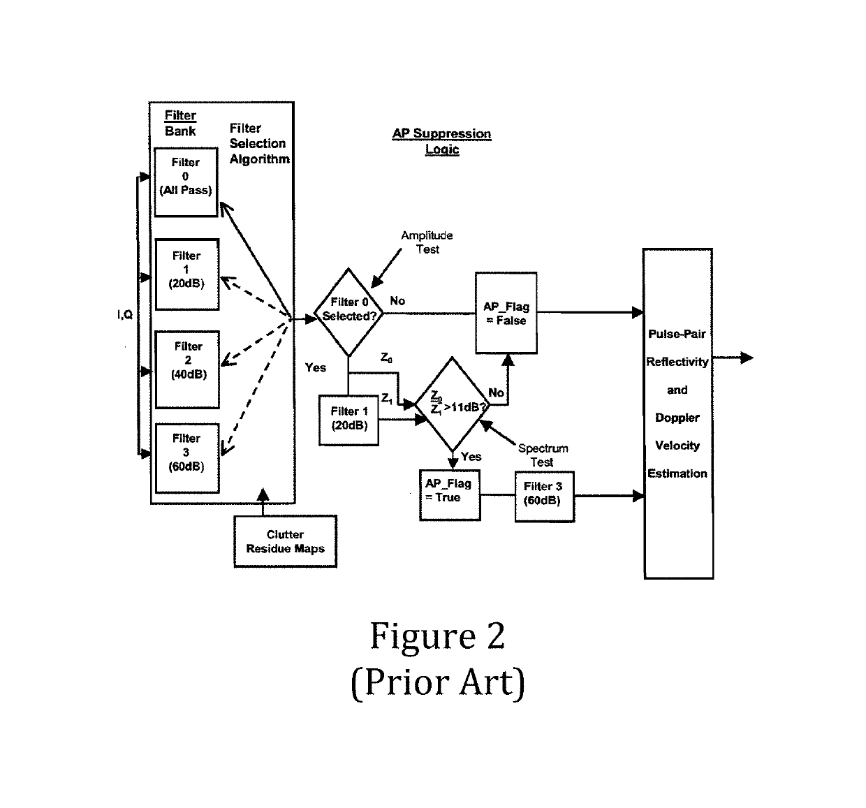
Fundamentally, these mitigation approaches have relied on spectral isolation (filtering) of perceived false and true weather, for which the full deployment results are not presently published or otherwise readily available.
ASR-11 modifications are currently underway, and although it is believed that these modification outcomes are somewhat positive, complete quantified data are not yet readily available.
There are several general limitations of the approaches used for the ASR-9 and ASR-11 AP mitigation.
(1) Firstly, a low velocity Doppler filters may mischaracterize slow moving weather as AP, and secondly (2), weather Doppler spreading is only more pronounced for more violent wind conditions.
Therefore, a filter approach based on the two factors here may mis-identify significant weather in many instances, incorrectly classifying real weather events as AP, for subsequent flagging and elimination.
Unfortunately, these methods require more time to update weather imagery: five minutes or so for a complete picture (NOAA, 2017), incorporated herein by reference, whereas ASR weather is required within seconds in the airport vicinity for ATC purposes.
It is therefore not practical to consider some elaborate approach that does not meet the latency for air traffic control, but instead to select a method that meets ASR requirements while adequately suppressing AP.

Method used


Image

  • Method and apparatus to minimize the effects of radar anomalous propagation for air traffic control
  • Method and apparatus to minimize the effects of radar anomalous propagation for air traffic control
  • Method and apparatus to minimize the effects of radar anomalous propagation for air traffic control

Examples


Embodiment Construction

[0025]The oldest terminal radar in the NAS inventory, the ASR-8, is currently undergoing a significant upgrade that replaces the radar's receiver processing chain and digitizes the older analog system. There are significant differences between the ASR-8 and the newer radars that essentially preclude a straightforward application of the previous modification approaches to mitigate anomalous propagation. Unlike the other two radar types, ASR-9 and -11, the ASR-8 does not have a separate weather channel to exclusively process meteorological conditions, and the older style Klystron transmitter employed does not have the stability considered suitable for precise Doppler filtering. Additionally, the existing ASR-8 Moving Target Indicator (MTI) interrogation stagger arrangement is not fully conducive to accurate Doppler filtering of replies. Moreover, it is believed that previous modification approaches used for the ASR-9 and ASR-11 may inherently have a false anomalous propagation declara...


PUM


Abstract

To minimize the effects of radar anomalous propagation for air traffic control, the range of a radar terminal is extended to build an extended clutter map, and the extended clutter map in turn is used to identify areas in radar returns where anomalous propagation may be falsely reporting ground clutter as weather. The extended clutter map includes a database of radar returns, and the method includes the step of comparing ongoing radar returns with the radar returns in the database to detect matches or correlations. To utilize existing radar terminals, the operating range of the existing terminal is extended with a higher-efficiency radar transmitter, higher-sensitivity receiver, or both. The performance improvement is in the range of 6 to 10 dB or more. The increased receiver sensitivity allows a greater volume of receive beam sampling and therefore an increased number of Doppler filter banks in which to detect and classify target primitives.

Description

REFERENCE TO RELATED APPLICATIONS[0001]This invention application claims priority to, and the benefit of, U.S. Provisional Patent Application Ser. No. 62 / 632,628, filed Feb. 20, 2018, the entire content of which is incorporated herein by reference.FIELD OF THE INVENTION[0002]This invention relates generally to Anomalous Propagation (AP) and, more particularly, to methods and apparatus for minimizing AP for air traffic control using extended clutter mapping.BACKGROUND OF THE INVENTION[0003]Anomalous Propagation (AP) is a phenomenon known throughout the field of radar engineering whereby certain meteorological conditions such as pressure, temperature and water vapor, can cause changes in the refractive index of the atmosphere, effectively bending the path of a radar's beam. Under certain conditions the radar beam can become trapped in the atmosphere, in an abnormality known as ducting, producing false returns from the ground. The presence and science of AP has been covered extensively...

Claims


Application Information

Patent Timeline
Patent Type & Authority Applications(United States)
IPC IPC(8): G01S13/95G01S13/91G08G5/00
CPCG01S13/953G01S13/91G08G5/0091G01S7/40Y02A90/10
Inventor SMITH, ALEXANDER E.DEYOE, ROBIN
Owner INTERSOFT ELECTRONICS INC
Learn More