
Method of harvesting radio-frequency energy, corresponding circuit and device

a radio frequency energy and corresponding circuit technology, applied in the field of radio frequency energy harvesting, can solve the problems of reducing the ability to transfer information from the tag, wideband arrangements exhibiting low sensitivity to external effects at the expense of communication range capabilities, etc., and achieve the effect of facilitating accumulating energy

Active Publication Date: 2019-08-22
STMICROELECTRONICS SRL
View PDF3 Cites 6 Cited by
  • Summary
  • Abstract
  • Description
  • Claims
  • Application Information

AI Technical Summary

Benefits of technology

The patent gives suggestions for improving RFID technology by using an automatic self-tuning system to avoid resonant frequency spreading and by extending the communication coverage range between an RFID tag and a reader. Additionally, the patent proposes using a combination of an antenna and an associated RF rectifier to increase energy collection.

Problems solved by technology

For instance, the material of the substrate may reduce the capability to transfer information from the tag to a reader, so that certain tags may be successfully queried only at short range due to the electrical properties of the material on which they are applied.
Pursuing a more uniform and reliable coverage range may lead to designing RFID antennas with low quality factors (e.g., Q in the 5-to-10 range), which may give rise to wideband arrangements exhibiting low sensitivity to external effects at the expense of the communication range capabilities.

Method used


Image

  • Method of harvesting radio-frequency energy, corresponding circuit and device
  • Method of harvesting radio-frequency energy, corresponding circuit and device
  • Method of harvesting radio-frequency energy, corresponding circuit and device

Examples


Embodiment Construction

[0035]In the ensuing description, one or more specific details are illustrated, aimed at providing an in-depth understanding of examples of embodiments of this description. The embodiments may be obtained without one or more of the specific details, or with other methods, components, materials, etc. In other cases, known structures, materials, or operations are not illustrated or described in detail so that certain aspects of embodiments will not be obscured.

[0036]Reference to “an embodiment” or “one embodiment” in the framework of the present description is intended to indicate that a particular configuration, structure, or characteristic described in relation to the embodiment is included in at least one embodiment. Hence, phrases such as “in an embodiment” or “in one embodiment” that may be present in one or more points of the present description do not necessarily refer to one and the same embodiment. Moreover, particular conformations, structures, or characteristics may be comb...


PUM


Abstract

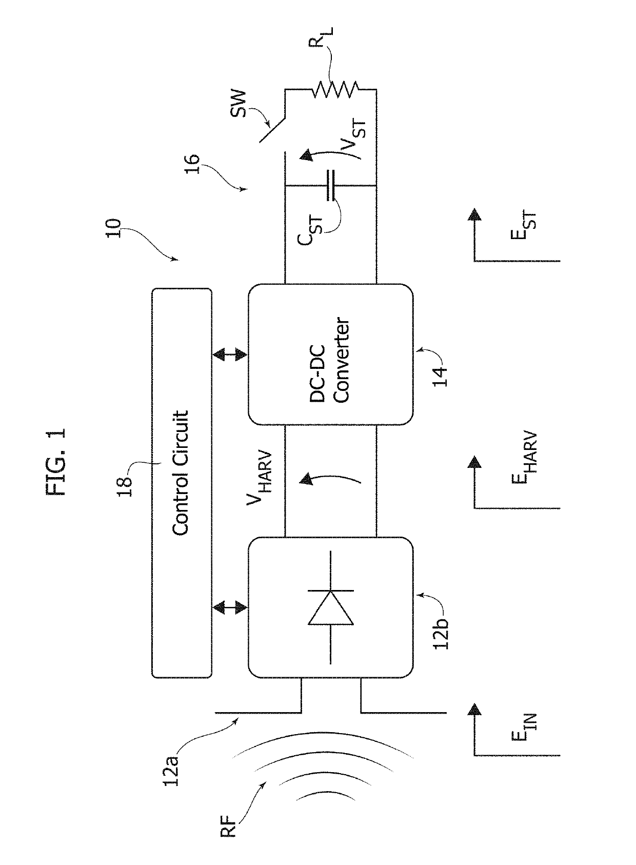
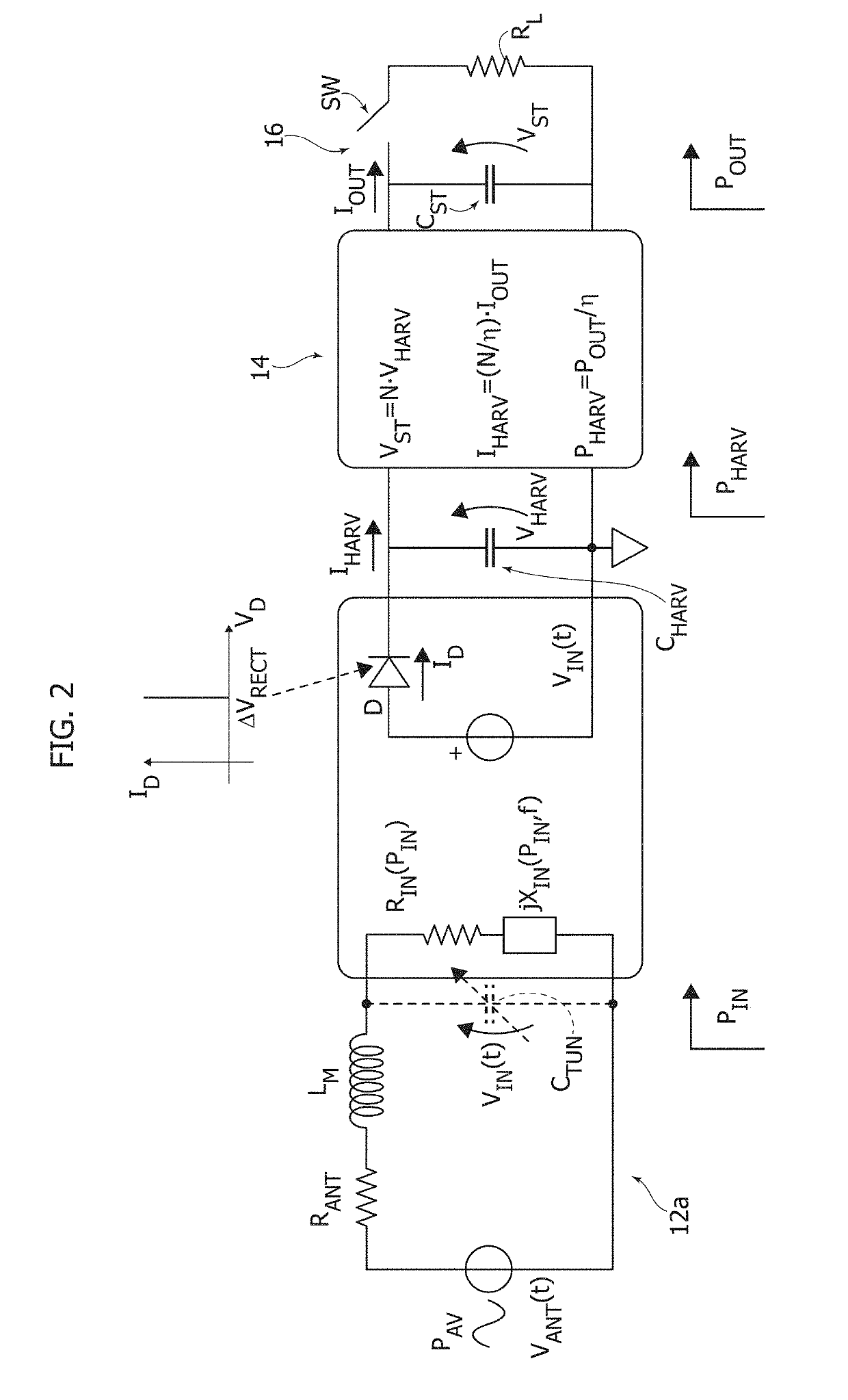
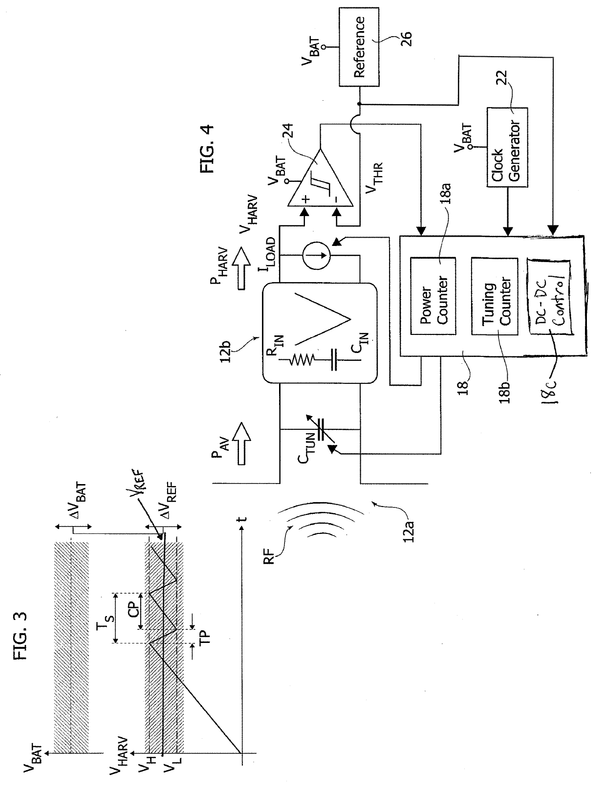
A radiofrequency harvester circuit may be used in a battery-less RFID device. The harvester circuit includes an antenna unit that captures radiofrequency signals and harvesting circuitry coupled to the antenna unit for collecting energy from the radiofrequency signals captured by the antenna unit. The antenna unit is selectively tunable at a plurality of tuning bands that are scanned by selectively tuning the antenna unit at different frequency bands and sensing respective values indicative of the power of radiofrequency signals captured by the antenna unit at the frequency bands scanned. A highest value out of said respective values for the power of radiofrequency signals as well as the frequency band in the plurality of tuning bands of the antenna unit providing the aforesaid highest value are identified and the harvester circuit is operated with the antenna unit tuned at the frequency band providing the highest value thus identified.

Description

BACKGROUNDTechnical Field[0001]The description relates to harvesting radio-frequency (RF) energy.[0002]One or more embodiments may be applied, e.g., to Radio-Frequency IDentification (RFID) devices, e.g., with the capability of operating in extreme low-power consumption conditions.Description of the Related Art[0003]In its current applications, Radio-Frequency IDentification (hereinafter, briefly RFID) technology involves the use of electronic tags placed on objects, humans or animals with the capability of relaying identifying information to an electronic reader by means of radio-waves.[0004]Automated toll payment systems or tracking systems capable of monitoring the progress of shipments, manufacturing processes and so on are exemplary of possible RFID applications.[0005]A simple and cheap realization of an RFID tag may involve a miniaturized silicon device applied (e.g., glued) onto a laminar substrate with an antenna layout imprinted thereon.[0006]The frequency response of the t...

Claims


Application Information

Patent Timeline
Patent Type & Authority Applications(United States)
IPC IPC(8): G06K7/10G06K19/07
CPCG06K7/10148G06K7/10158G06K19/0726G06K19/0709H02J50/20
Inventor CASELLI, MICHELEBONI, ANDREARONCHI, MARCO
Owner STMICROELECTRONICS SRL
Learn More