Leak inspection assistance device and leak inspection method using same

a technology of leak inspection and assistance device, which is applied in the direction of fluid tightness measurement, separation processes, instruments, etc., can solve the problems of large-scale work performed by multiple people and the possibility of overlooking leaks, so as to reduce the cost burden of leak inspection, accurately identify, and accurately perform leak inspection of the filter

Active Publication Date: 2019-08-29
AIREX
View PDF0 Cites 3 Cited by
  • Summary
  • Abstract
  • Description
  • Claims
  • Application Information

AI Technical Summary

Benefits of technology

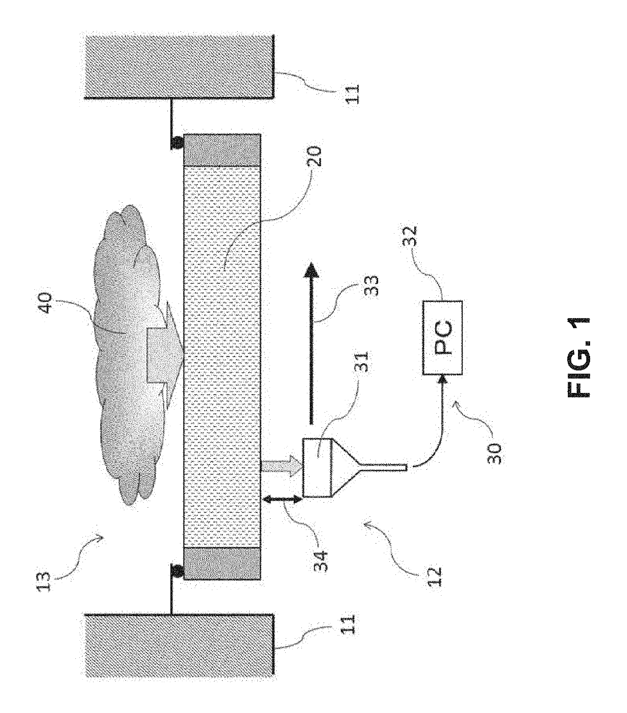
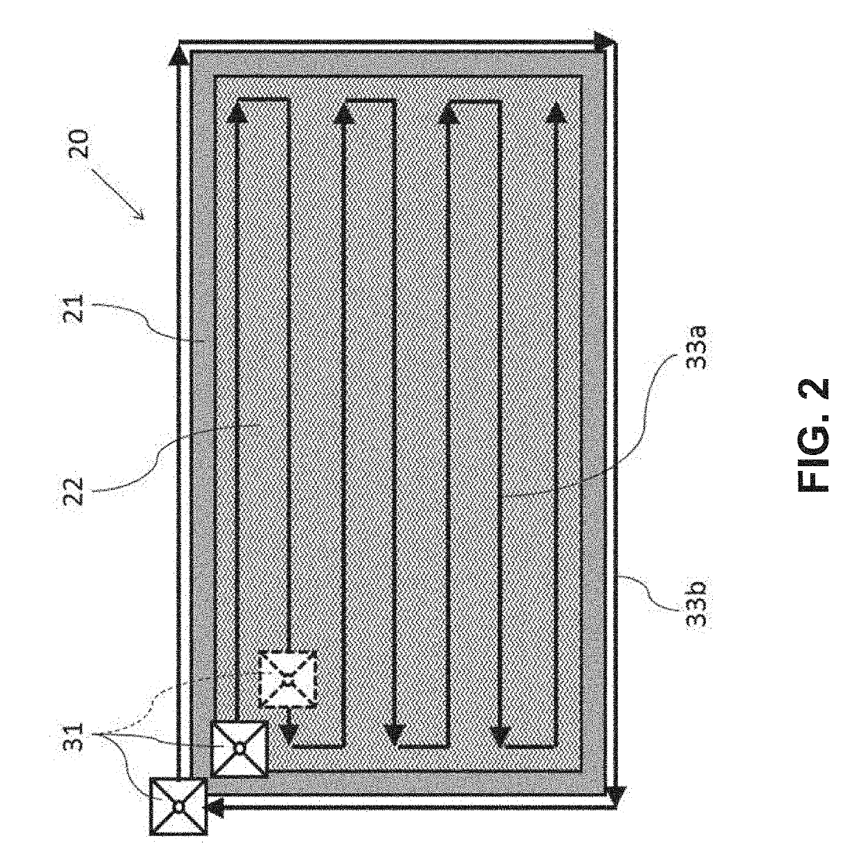
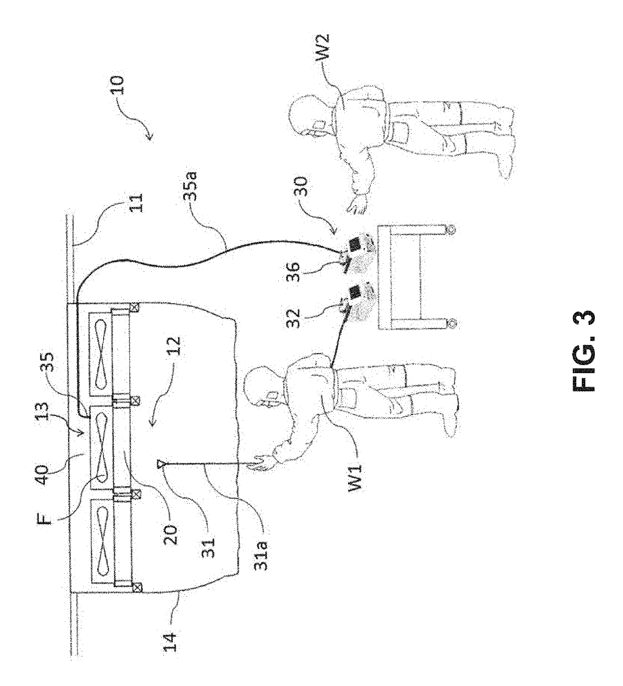
[0032]According to the above-described configuration, the leak inspection assistance device of the present invention has the projection device. This projection device projects the suction point of the suction probe onto the surface of the filter provided on the wall surface of the working chamber. The suction point projected onto the surface of the filter moves along the surface of the filter in the X-Y axis directions orthogonal each other at a fixed interval and a fixed speed. At this moment, what is required for a worker who performs the leak inspection is enabling the suction probe to travel in accordance with the movement of the suction point.
[0033]Consequently, the suction probe can be moved along the surface of the filter at a fixed interval and a fixed speed, and the leak inspection of the filter can be accurately performed. Further, when this leak inspection assistance device is adopted, a normal leak inspection device can be used, and a cost burden of the leak inspection can be reduced without requiring a scanning robot, large-scale equipment, an incidence work, and the like.
[0034]Furthermore, according to the above-described configuration, in the leak inspection assistance device of the present invention, leak information detected by the fine particle detector adjunct to the leak inspection device may be projected onto the surface of the filter through the projection device. When the leak information is projected onto the surface of the filter, the same worker can confirm the leak information while performing scanning with the suction probe, and a leak position can be accurately identified. Consequently, in addition to the above-described effect, the accurate leak inspection can be carried out with a small number of workers.
[0035]Thus, according to each configuration described above, it is possible to provide the leak inspection assistance device which can use the normal leak inspection device in the leak inspection of the filter in the clean room, has a small cost burden since a scanning robot, large-scale equipment, an incidence work, and the like are not required, and enables performing the accurate leak inspection with a small number of workers.
[0036]Further, according to the above-described configuration, in the leak inspection assistance device of the present invention, the projection device has the projection correcting means. This projection correcting means acts to correct a positional relationship between a position of the projection device directly or indirectly mounted on the floor surface of the working chamber and the surface of the filter. This projection correcting means performs the correction in such a manner that an outline of the scanning line shown in a projection image projected onto the surface of the filter from the projection window of the projection device is projected in conformity with the outline of the filter.
[0037]When the outline of the scanning line shown in the projection image conforms with the outline of the filter in this manner, the projected suction point can move along the surface of the filter at a fixed interval and a fixed speed. Consequently, even if a position of the projection device directly or indirectly mounted on the floor surface of the working chamber deviates from a position immediately below the filter, the accurate leak inspection can be carried out. Thus, each of the above-described effects can be more specifically exerted.

Problems solved by technology

In such leak inspection directions, since maintaining a scanning speed or a scanning interval of the suction probe constant is difficult, an accuracy of the leak inspection varies, and a possibility of overlooking the leak is high.
Moreover, at least two persons or more are required as the workers, which leads to a large-scale work performed by multiple persons.

Method used


Image

  • Leak inspection assistance device and leak inspection method using same
  • Leak inspection assistance device and leak inspection method using same
  • Leak inspection assistance device and leak inspection method using same

Examples


example 1

[0075]In this Example 1, a description will be given on a method for adapting the projection image 53 to the surface of the HEPA filter 20 by using a projection correcting function of the leak inspection assistance device 50 in the configuration of the leak inspection device 30 and the leak inspection assistance device 50 shown in FIG. 4.

[0076]In the leak inspection assistance device 50, the projection image 53 which is projected from the projector 51 is programed and loaded in the personal computer 52 in advance. When information such as a number of the HEPA filter which is to be subjected to the leak inspection, a longitudinal / lateral size, a size of the mounting frame, a size of the suction opening of the suction probe, and the like is input to this program, settings and arrangement of the scanning lines 33a and 33b of the projection image 53, a speed of the suction point 54, and the like are set.

[0077]FIG. 6 is a schematic view showing how a positional relationship between the p...

example 2

[0084]In this Example 2, a description will be given as to a method for conforming a projection image 53 to a surface of a HEPA filter 20 with the use of a filter position detection device of the leak inspection assistance device 50 in the configuration of the leak inspection device 30 and the leak inspection assistance device 50 shown in FIG. 4.

[0085]In the leak inspection assistance device 50, a projection image 53 projected from a projector 51 is programmed and loaded in a personal computer 52 in advance. When information such as a number of the HEPA filter which is to be subjected to the leak inspection, a longitudinal / lateral size, a size of a mounting frame, a size of a suction opening of a suction probe, and the like is input to this program, settings and arrangement of scanning lines 33a and 33b of the projection image 53, a speed of a suction point 54, and the like are set.

[0086]FIG. 7 is a schematic view showing how a positional relationship between the projection device a...


PUM

PropertyMeasurementUnit
particle diameteraaaaaaaaaa
sizeaaaaaaaaaa
scanning speedaaaaaaaaaa

Abstract

Provided are a leak inspection assistance device and a leak inspection method using the same which enable using a normal leak inspection device in a leak inspection of filters in a clean room, have a small cost burden since a scanning robot, large-scape equipment, an incidental work, and the like are not required, and enable performing the accurate leak inspection with a small number of workers.
A projection device which projects a suction point of a suction probe adjunct to a leak inspection device which performs a leak inspection onto a surface of a filter in a clean room in such a manner that the suction point moves in X-Y axis directions orthogonal to each other along the surface of the filter at a fixed interval and a fixed speed is provided, and a worker uses the suction probe for scanning in accordance with movement of the suction point.

Description

TECHNICAL FIELD[0001]The present invention relates to a leak inspection assistance device which is used together with a leak inspection device in leak inspections of an air cleaning filter installed in a clean environment such as a clean room. Further, the present invention relates to a leak inspection method using the leak inspection assistance device.BACKGROUND ART[0002]As regards a work performed in a clean atmosphere, e.g., a work in a production process of drugs and medicines or a work in a production process of semiconductors or electronic components, the work is performed in a clean working environment inside of which is maintained in a dust-free / aseptic condition so that contaminant cannot enter from an external environment. As such a working environment, a clean room is generally used. In this clean room, a worker wearing dust-free clothes performs a work.[0003]Clean air is supplied into this clean room from an air supply device through a HEPA filter or a ULPA filter (which...

Claims


Application Information

Patent Timeline
Patent Type & Authority Applications(United States)
IPC IPC(8): G01M3/02B01D46/44B01D46/00B01D46/46
CPCG01M3/02B01D46/442B01D2273/18B01D46/46B01D46/009G01M3/38G01N15/08B01D46/42G01M3/04G01M3/00
Inventor KAWASAKI, KOJI
Owner AIREX
Why Eureka
Try Eureka