Radar sensor for motor vehicles

a technology for radar sensors and motor vehicles, applied in the direction of instruments, measurement devices, and reradiation, can solve the problems of increasing computation complexity, increasing computation complexity, and cognitive radar approaches becoming more and more significant, and achieve the effect of greater accuracy

Active Publication Date: 2019-08-29
ROBERT BOSCH GMBH
View PDF0 Cites 19 Cited by
  • Summary
  • Abstract
  • Description
  • Claims
  • Application Information

AI Technical Summary

Benefits of technology

[0013]An object of the present invention is to provide a method that allows distances and relative speeds to be measured unequivocally and with even greater accuracy.
[0016]In the radar sensor according to the present invention, the individual wave trains, which, for example as in the related art, can be constituted by frequency ramps having a constant and identical slope and identical frequency excursion, or, e.g., also by OFDM symbols, are no longer equidistant, but instead the transmission times are varied as a function of the respective center frequency, in such a way that the aforementioned relationship is satisfied. The consequence is that the product of the transmission time Tj of the j-th wave train and the center frequency fc,j, which determines the phase profile over the slow time, is a linear function of the ramp index j. The result is to eliminate from the phase profile the nonlinearities that are produced in the related art by the variation in the center frequencies fc,j and that would result, in the context of a Fourier transform over the slow time, i.e., over the index j, in a broadened peak and thus in a degradation of measurement accuracy and separation capability, in particular in terms of speed measurement.
[0017]The present invention thus makes it possible to vary the center frequencies as necessary, for example in order to optimize measurement accuracy and separation capability in the context of distance measurement or, in a cognitive radar system, to avoid interference from other radar signals, without having to consider what effect those changes in center frequency might have on the speed measurement.

Problems solved by technology

Greater bandwidth requires an increase in analog to digital converter (ADC) rates, and increases computation complexity.
This approach for fast-chirp systems therefore represents a compromise between improving the distance estimate and degrading the speed estimate.
Cognitive radar approaches are also becoming more and more significant, since the number of radar sensors in the automotive sector is continually increasing and the probability of interference resulting from other radar sensors thus rises.
Here as well, the problem occurs that the phase profile over the slow time depends on the carrier frequency, on the distance, and on the speed, and the change in carrier frequency results in a nonlinear change in phase.
The consequence is that the speed estimate (for instance, using Fourier evaluation) becomes degraded or is not possible at all.

Method used


Image

  • Radar sensor for motor vehicles
  • Radar sensor for motor vehicles
  • Radar sensor for motor vehicles

Examples


Embodiment Construction

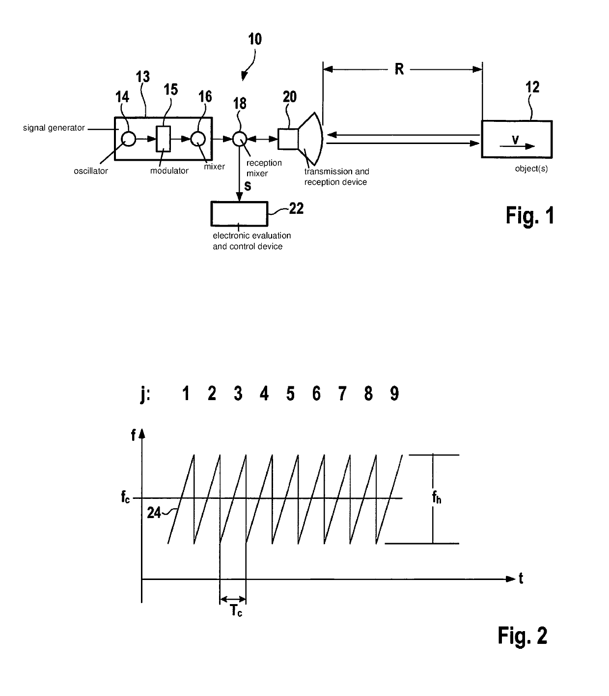
[0031]FIG. 1 is a simplified block diagram depicting an FMCW radar sensor 10 that, for example, is installed at the front of a motor vehicle and serves to measure distances R and relative speeds v of objects 12, for example of preceding vehicles. Radar sensor 10 has a signal generator 13 having an oscillator 14, a modulator 15, and a mixer 16 that mixes wave trains generated by the modulator up into a high-frequency band by mixing with a respective carrier frequency, and thereby generates a radar signal that is to be transmitted. Alternatively, signal generation can occur, depending on the wave train, directly with the aid of an oscillator. This radar signal is then supplied via a transmission and reception mixer 18 to a transmission and reception device 20, from which the signal is sent out toward object 12. The signal reflected at the object is received by transmission and reception device 20 and mixed, in transmission and reception mixer 18, with a portion of the transmitted sign...


PUM


Abstract

A radar sensor for motor vehicles, having a signal generator that is configured to generate a radar signal that contains a cyclically repeating sequence of N wave trains, where j=1, . . . , N, which are transmitted successively at time intervals T′c,j and which occupy respective frequency bands that differ from one another in terms of their center frequencies fc,j, wherein the relationship applicable to the time intervals T′c,j and the center frequencies fc,j is: T′c,j*fc,j=X, where the parameter X is constant.

Description

FIELD[0001]The present invention relates to a radar sensor for motor vehicles, having a signal generator that is configured to generate a radar signal that contains a cyclically repeating sequence of N wave trains Wj, where j=1, . . . , N, which are transmitted successively at time intervals T′c,j and which occupy respective frequency bands that differ from one another in terms of their center frequencies fc,j.BACKGROUND INFORMATION[0002]Radar systems for measuring a distance, relative speed, and angle of objects (for example, vehicles and obstacles) are increasingly being used in motor vehicles for safety functions and convenience functions. The accuracy of radar measurements in terms of distance, speed, and angle plays an increasingly important role here, since driver assistance systems and autonomous driving functions require maximally accurate environmental detection.[0003]A further important criterion is the separation capability of the radar sensor in all three parameters, i.e...

Claims


Application Information

Patent Timeline
Patent Type & Authority Applications(United States)
IPC IPC(8): G01S13/34G01S13/93G01S7/02G01S13/931
CPCG01S13/347G01S13/931G01S2007/356G01S13/343G01S7/023G01S7/356G01S7/0232G01S7/0234
Inventor HAKOBYAN, GORARMANIOUS, KARIM ADEL DAWOODSCHOOR, MICHAEL
Owner ROBERT BOSCH GMBH
Why Eureka
Try Eureka