Virtual image display device

a virtual image and display device technology, applied in the field of virtual image display devices, can solve the problems of increasing the burden on the optical system, increasing the design restrictions, and the above-described problem of an incident angle of light possibly becoming remarkable, and achieve the effect of reducing size or thickness and being easy to moun

Active Publication Date: 2019-08-29
SEIKO EPSON CORP
View PDF4 Cites 14 Cited by
  • Summary
  • Abstract
  • Description
  • Claims
  • Application Information

AI Technical Summary

Benefits of technology

[0006]In the above-described virtual image display device, the first lens and the second lens are configured to be bonded, and by configuring a light emitting side of the first lens and a light incident side of the second lens as flat surfaces, reduction in size or thickness is achieved. Additionally, by configuring as the flat surfaces, for example, various optical elements such as an optical element for folding light can be easily mounted. Further, a condition about a light incident angle from the image element also can be relaxed, for example, compared to a case of a lens including a curved surface such as a convex spherical surface lens. On the other hand, by providing the half mirror in the bonding portion between the convex surface and the concave surface in an optical path to give power in folding the optical path, an image with a wide angle of view can be formed.

Problems solved by technology

However, in the HMD, when reduction in size or thickness of a device is attempted while a thin optical system with a wide angle of view is achieved, a burden on the optical system increases.
That is, restrictions for design increase.
Especially, when an image is expanded and projected by a small image element, the above-described problem about an incident angle of light possibly becomes remarkable.

Method used


Image

  • Virtual image display device
  • Virtual image display device
  • Virtual image display device

Examples


Embodiment Construction

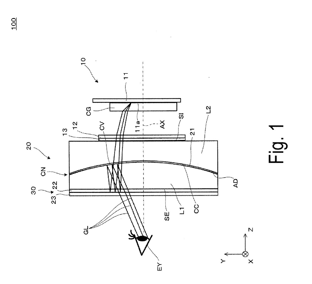
[0021]A virtual image display device according to an exemplary embodiment of the invention will be described below in detail with reference to FIG. 1 and the like.

[0022]As conceptually illustrated in FIG. 1, a virtual image display device 100 of the exemplary embodiment includes an image display device 10 as an image element (image display unit) and an enlargement optical system 20, and serves as a virtual image display device capable of causing an observer or a user wearing the virtual image display device 100 to visually recognize image light (image light) by a virtual image, that is, a head-mounted display (HMD). Here, FIG. 1 conceptually illustrates a state viewed from a side in a case in which the observer wears the virtual image display device 100, and an optical axis AX of an optical system in the virtual image display device 100 is in a Z direction. Additionally, among in-plane directions of a surface orthogonal to the Z direction, a horizontal direction that is a right-left...


PUM


Abstract

A first lens and a second lens are bonded, and each of a light emitting plane and a light incident plane is a flat surface to shorten a configuration in an optical axis direction, and simultaneously, various optical elements such as a transmission/reflection selection member and the like can be mounted on a flat surface portion. Further, by providing a half mirror in a bonding portion between a convex surface and a concave surface to give power in folding an optical path, an image with a wide angle of view can be formed.

Description

BACKGROUND1. Technical Field[0001]The invention relates to a virtual image display device that provides, to an observer, an image formed by an image element and the like, in a state of being mounted on the observer.2. Related Art[0002]As an virtual image display device or a head mounted type display device such as a head-mounted display to be mounted on the head of an observer, for example, as described in JP-A-8-327940, a closed type with a wide visual field that achieves a thin optical system with a wide angle of view by providing a partial optical folding portion utilizing a half mirror has been known. Note that, the head-mounted display is also described as an HMD in the following.[0003]However, in the HMD, when reduction in size or thickness of a device is attempted while a thin optical system with a wide angle of view is achieved, a burden on the optical system increases. That is, a curved surface shape or a refractive index of a lens configuring the optical system is preferab...

Claims


Application Information

Patent Timeline
Patent Type & Authority Applications(United States)
IPC IPC(8): G02B27/28G02B5/30G02B27/01
CPCG02B27/286G02B27/0172G02B5/3025G02B27/0101G02B17/086G02B27/28
Inventor TAKAGI, MASAYUKITAKEDA, TAKASHIKOMATSU, AKIRAMIYAO, TOSHIAKIYAMAGUCHI, TOKITO
Owner SEIKO EPSON CORP
Why Eureka
Try Eureka