
Receiver arrangement for the reception of light impulses, lidar module and method for receiving light impulses

a technology of light impulse and receiver, which is applied in the direction of reradiation, measurement devices, instruments, etc., can solve the problems of reducing resolution and high sampling rate of 10 ghz, and achieve the effect of reducing the resolution of distance determination

Active Publication Date: 2019-09-12
MICROVISION
View PDF0 Cites 34 Cited by
  • Summary
  • Abstract
  • Description
  • Claims
  • Application Information

AI Technical Summary

Benefits of technology

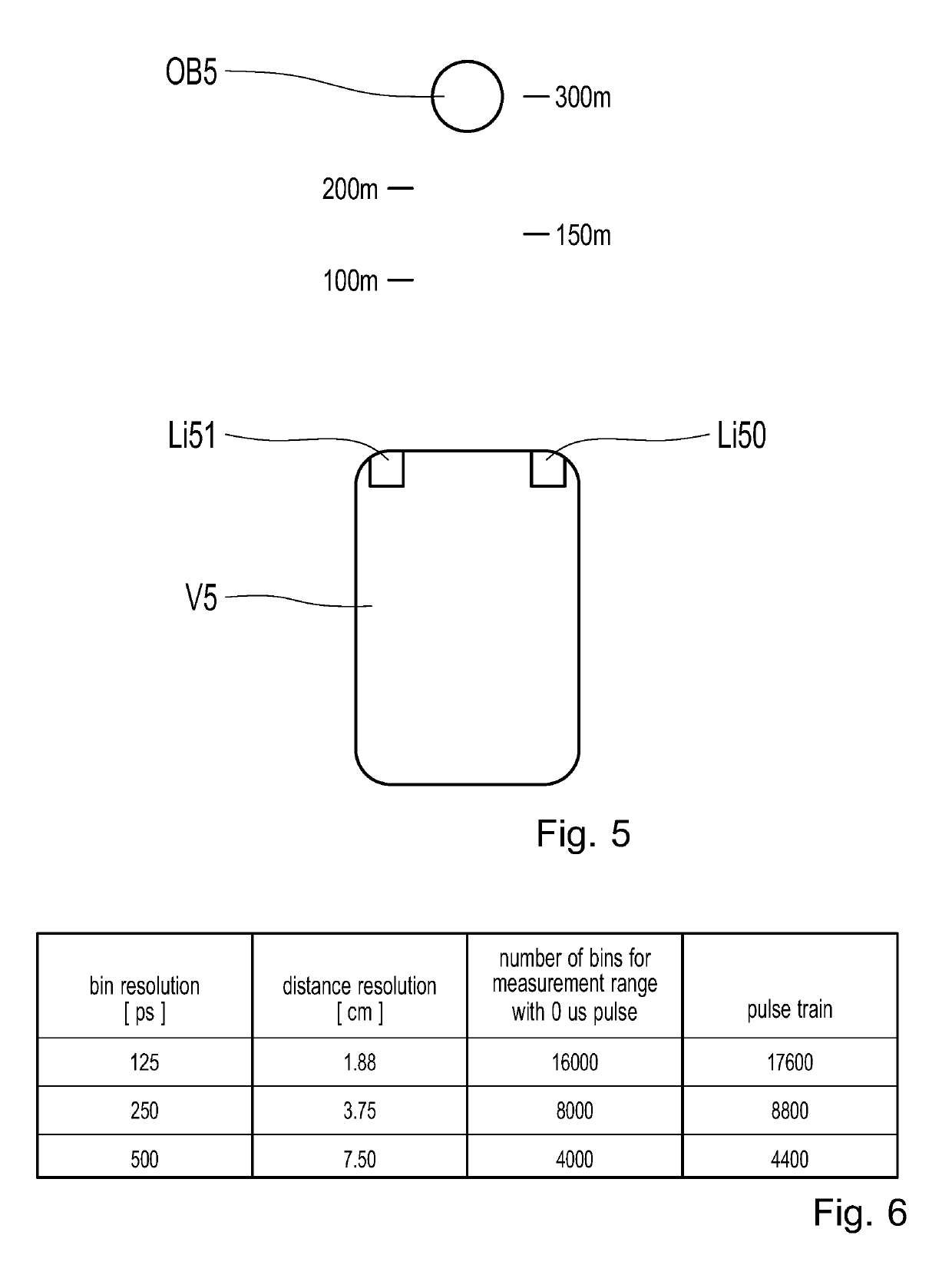
The invention is a receiver assembly and associated method for measuring the distance between a receiver and an object that reflects light pulses. The system uses time-correlated photon counting with a histogram to determine the time of flight of the light pulse and calculates the distance based on the electric signal. The receiver assembly reduces the resolution of the distance determination to save memory space and reduce costs. Additionally, the reduced distance determination uncertainty is negligible when the object is over 100 meters away. The invention is particularly useful in vehicles for accurately measuring distances and object classifications.

Problems solved by technology

As a result of the multiple repetitions of the measurements and the acquisitions in a histogram, the desired signal can be amplified with respect to disruptive ambient light, although a high sampling rate of 10 GHz currently cannot be implemented inexpensively.
This results in a reduction in the resolution.

Method used


Image

  • Receiver arrangement for the reception of light impulses, lidar module and method for receiving light impulses
  • Receiver arrangement for the reception of light impulses, lidar module and method for receiving light impulses
  • Receiver arrangement for the reception of light impulses, lidar module and method for receiving light impulses

Examples


Embodiment Construction

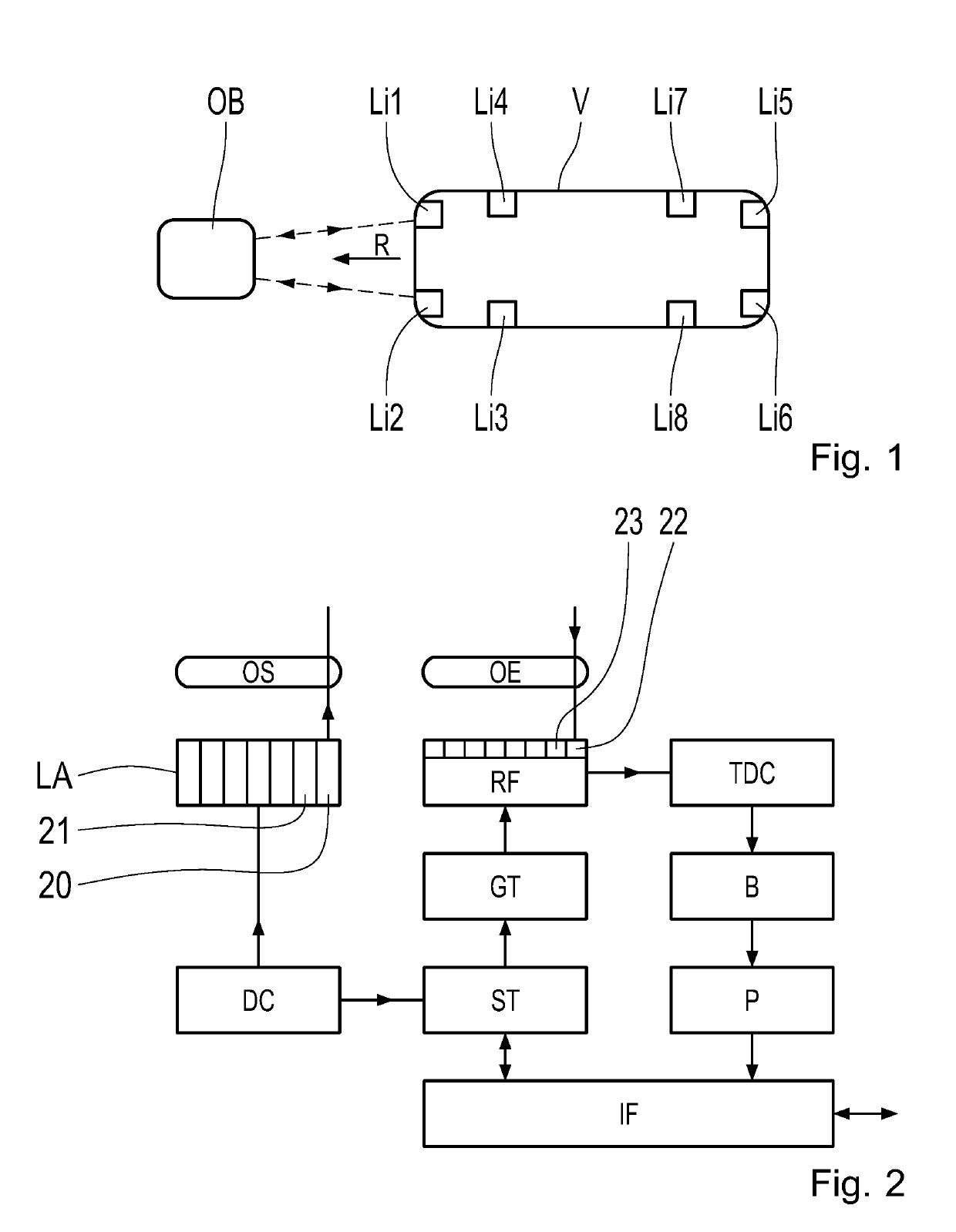
[0036]FIG. 1 shows a vehicle V, moving in the direction R. The vehicle V contains the lidar modules Li1 to Li8. These lidar modules record the surroundings of the vehicle V. As a result, the object OB is detected by the lidar module Li1. As a result of a distance determination and a corresponding characterization of the object based on the movement parameters, it is possible to determine the probability of a collision, and to influence the movement of the vehicle V accordingly, in order to avoid colliding with the object OB.

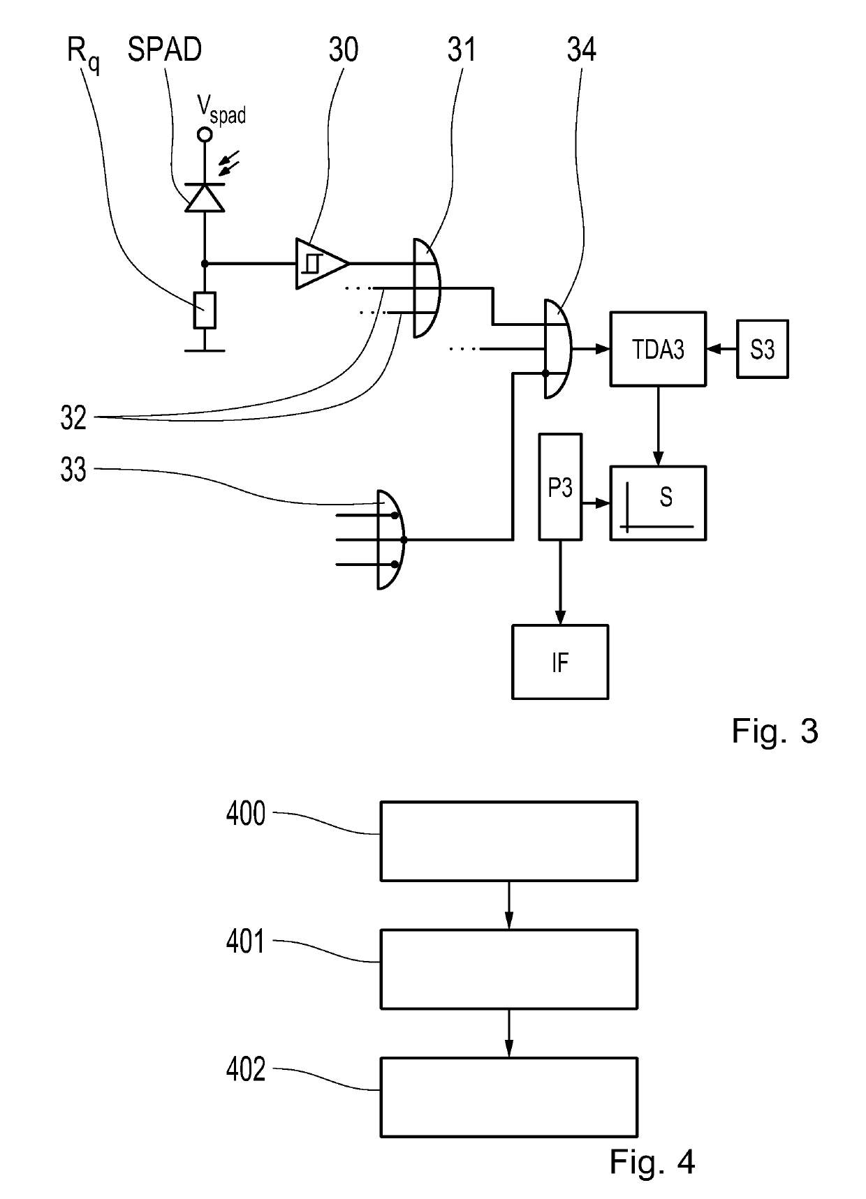
[0037]The lidar modules Li1 to Li8 have a receiver assembly according to the invention, and a transmitter device, as described above, with a laser array, which emits laser pulses, in order to then receive the laser pulses reflected by the object OB with an SPAD array, and then evaluate them accordingly with the time-correlated photon counting, in order to determine the distance between the object OB and the vehicle V. A time of flight method is used for this.

[003...


PUM


Abstract

A receiver assembly for receiving light pulses, a lidar module containing such a receiver assembly, and a method for receiving light pulses are proposed. There is at least one photosensitive receiver (SPAD) therein, which converts the light pulses into an electric signal. An evaluation circuit is connected to the receiver, which determines a distance between the receiver assembly and at least one object that reflects the light pulses from the electric signal, by means of a time-correlated photon counting with at least one histogram, via a time of flight of the light pulse. The evaluation circuit is configured to reduce the resolution of the distance determination starting at no further than a predetermined distance.

Description

FIELD[0001]The invention relates to a receiver assembly for receiving light pulses, a lidar module, and a method for receiving light pulses as specified in the independent claims.DESCRIPTION OF RELATED ART[0002]A device and a method with which it is possible to make a three dimensional recording of objects by means of a two dimensional planar laser field is known from U.S. Pat. No. 9,268,012 B2. Groups of individual lasers can also be used in this laser field. These lasers are so-called VCSELs (Vertical Cavity Surface Emitting Lasers) and are normally produced as semiconductors. A corresponding optics element is disclosed, which aligns the laser beams in parallel. Furthermore, photodetectors are used, arranged in random or specific patterns. A micro-lens array is located in front of the photodetectors, such that each photodetector corresponds to a specific micro-lens. Such micro-lenses are also placed in front of the laser field.SUMMARY[0003]The receiver assembly according to the in...

Claims


Application Information

Patent Timeline
IPC IPC(8): G01S7/486G01S7/484G01S7/4863G01S7/4865G01S17/931
CPCG01S7/4863G01S7/484G01S17/88G01S7/4816G01S7/486G01S17/931G01S7/4815G01S7/4865
Inventor BEUSCHEL, RALFKABUK, ÜNSAL
Owner MICROVISION
Learn More