Cell-balancing method and battery management system performing the same

a cell-balancing and management system technology, applied in battery/fuel cell control arrangement, secondary cell servicing/maintenance, instruments, etc., can solve the problems of complex control, energy consumption of discharging, radiation of heat, etc., and achieve the effect of reducing the balancing tim

Active Publication Date: 2019-09-12
SAMSUNG SDI CO LTD
View PDF0 Cites 2 Cited by
  • Summary
  • Abstract
  • Description
  • Claims
  • Application Information

AI Technical Summary

Benefits of technology

[0010]The present disclosure provides a cell-balancing method for reducing a balancing time while maintaining a heat radiation performance of a substrate, and a battery management system for performing the same.

Problems solved by technology

The passive cell-balancing method uses a simple control method or a simple control circuit, but power generated by a discharging is consumed through heat, so radiation of heat becomes an important issue.
The active cell-balancing method consumes less power than the passive type to thus provide better efficiency, but its control is complicated, and it generally uses more components to configure a cell-balancing control circuit.
Generally, a method for increasing a balancing current may be used so as to reduce the time used to the cell-balancing, but when the balancing current increases, generation of heat caused by power consumption also increases.
Increasing heat radiation performance of the substrate may result in the increase of a size of the substrate and a material cost.
In addition, when the cell-balancing circuit is actually designed, the discharge current may be designed to an acceptable level to enable the heat radiation performance of the substrate, even when all of the cells are simultaneously balance-discharged, so there is a limit in increasing the balancing current for reducing the cell-balancing time.

Method used


Image

  • Cell-balancing method and battery management system performing the same
  • Cell-balancing method and battery management system performing the same
  • Cell-balancing method and battery management system performing the same

Examples


first embodiment

[0094]A cell-balancing method according to the present disclosure will now be described with reference to FIG. 6 to FIG. 8.

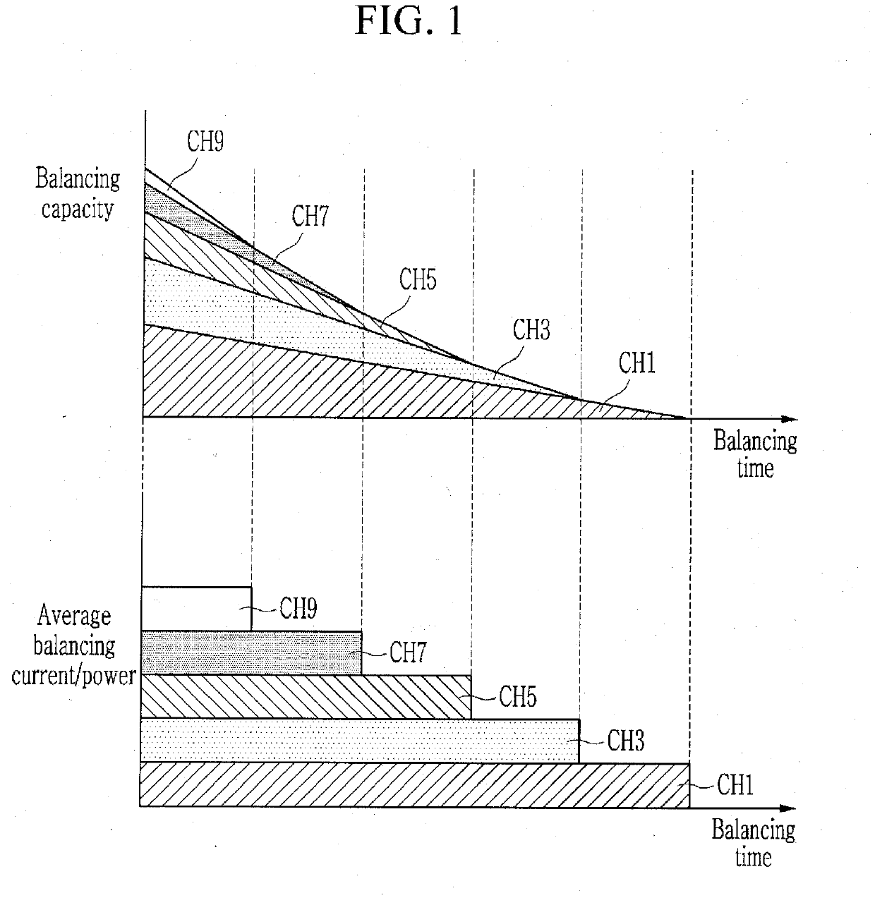
[0095]FIG. 6 shows a cell-balancing method according to a first embodiment of the present disclosure. FIG. 7 and FIG. 8 show examples of balancing capacity and a changing trend of average balancing current / power when a cell-balancing control method according to a first embodiment of the present disclosure is used. FIG. 9 shows an example of a related art cell-balancing control timing diagram, and FIG. 10 shows an example of a cell-balancing control timing diagram when a cell-balancing method according to a first embodiment of the present disclosure is applied.

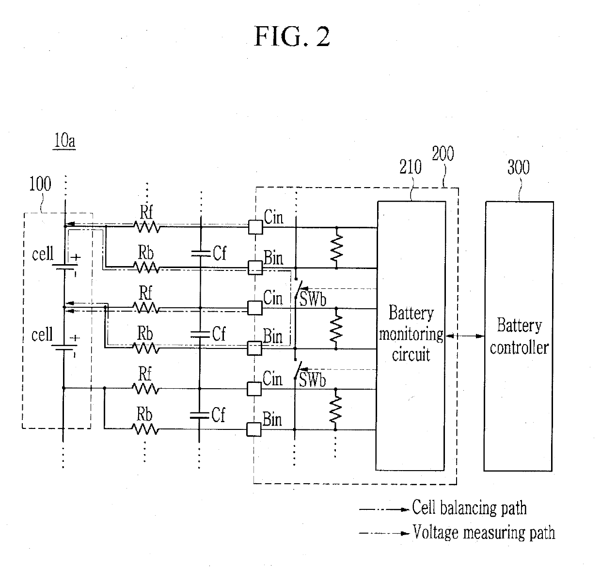
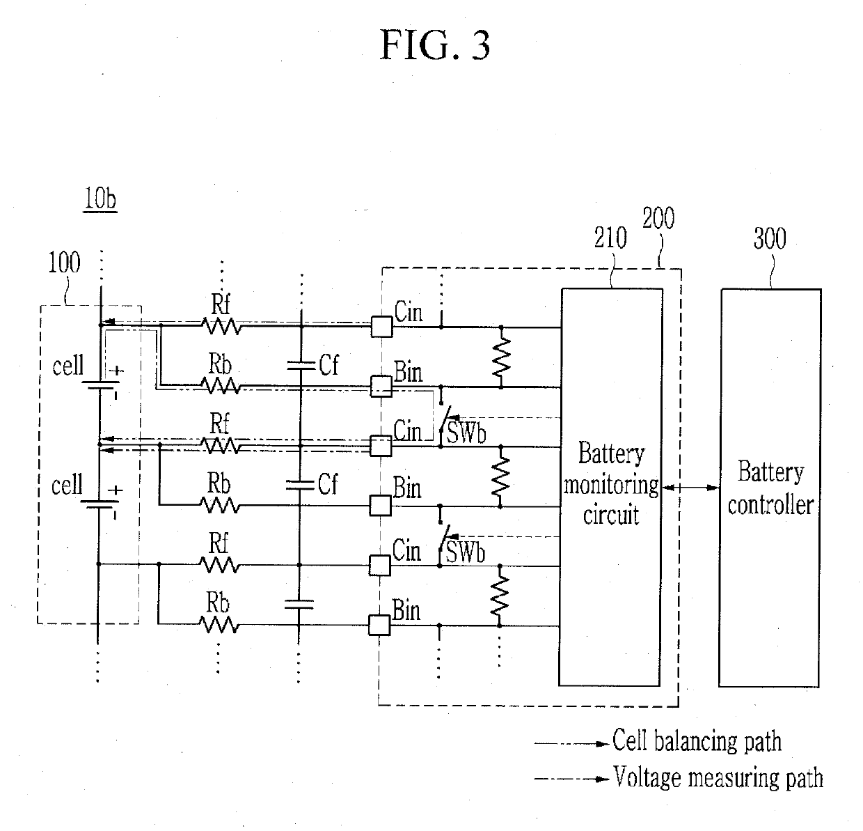
[0096]Referring to FIG. 6, according to a first embodiment of the present disclosure, the battery packs 10a, 10b, and 10c periodically detect a cell voltage of each cell configuring the battery module 100 through the battery IC 200 (S100).

[0097]In S100, the battery IC 200 includes a voltage-detecting circui...

second embodiment

[0123]To solve the above-noted problem, in the cell-balancing method according to the present disclosure, while the duty cycle of the balancing switches (SWb) is based on-the balancing capacity ratio among the balancing target cells, the duty cycle of the balancing switches (SWb) is scaled so that sums of duty cycles of the two adjacent cells may be less than or equal to a maximum of 100%. Therefore, one balancing on one of two adjacent cells is turned on while the balancing of the other is turned off to prevent two adjacent cells from simultaneously being turned on. Accordingly, it becomes possible to set the duty cycle of one cell to be greater than 50% through a duty scaling, thereby increasing the cell-balancing efficiency.

[0124]A cell-balancing method according to a second embodiment of the present disclosure will now be described in detail with reference to FIG. 11 to FIG. 14.

[0125]FIG. 11 shows a cell-balancing method according to a second embodiment of the present disclosure...

third embodiment

[0156]To solve the issue of heat generation, a cell-balancing method according to the present disclosure described below may acquire the heat radiation performance of the substrate on which a cell-balancing circuit is located by managing power consumption of all of the balancing resistors in addition to individual power consumption of each balancing resistor.

[0157]Power generated by the balancing current generates heat by the balancing resistor, and the heat generated by the balancing resistor is mostly radiated through a wiring pattern of the substrate according to a thermal conduction method. Therefore, the configuration of the substrate provided around the balancing resistor or the wiring pattern may influence the heat radiation performance. The balancing resistors are close to each other on the actual substrate. Hence, the heat radiation performance of the substrate may be obtained by managing the power consumption of the balancing resistors in addition to individual power consu...


PUM


Abstract

A battery management system may include a plurality of balancing resistors respectively forming balancing discharging paths of cells connected in series to each other, a plurality of balancing switches respectively connected between the cells and the balancing resistors, and configured to control cell-balancing of each of the cells, a voltage-detecting circuit for detecting respective cell voltages of the cells, and a battery controller for acquiring respective balancing capacities of the cells based on the cell voltages, for obtaining duty cycles of the balancing switches according to the balancing capacities, and for scaling the duty cycles of the balancing switches according to a sum of duty cycles of two adjacent cells from among the cells.

Description

CROSS-REFERENCE TO RELATED APPLICATION[0001]This application claims priority to, and the benefit of, Korean Patent Application No. 10-2018-0026458 filed in the Korean Intellectual Property Office on Mar. 6, 2018, the entire contents of which are incorporated herein by reference.BACKGROUND1. Field[0002]Embodiments disclosed herein relate to a cell-balancing method and a battery management system for performing the same.2. Description of the Related Art[0003]Recently, according to strengthening of environmental regulations including CO2 regulations, interest in environmentally-friendly vehicles has been increasing. Accordingly, vehicle companies have been actively researching and developing pure electrical vehicles and hydrogen vehicles, as well as hybrid and plug-in hybrid vehicles.[0004]A high-voltage battery for storing electrical energy obtained from various energy sources is applied to the environmentally-friendly vehicles. The high-voltage battery includes a plurality of cells c...

Claims


Application Information

Patent Timeline
Patent Type & Authority Applications(United States)
IPC IPC(8): H02J7/00
CPCH02J7/0016H02J7/0021Y02T10/70H02J7/0048Y02E60/10H01M10/425G01R31/396G01R31/3835G01R31/3648B60L58/20H01M2010/4271B60Y2200/92B60Y2200/91H02J7/0024H02J7/0025H02J7/0014H02J7/007182
Inventor HIDAKA, TAKAOKIM, HWA-SU
Owner SAMSUNG SDI CO LTD
Why Eureka
Try Eureka