A semi-open cavity resonant photoacoustic cell

A photoacoustic cell and sound wave technology, applied in color/spectral characteristic measurement, material analysis through optical means, instruments, etc., can solve the problems of increasing the difficulty of laser collimation, increasing system noise, and limited space for improvement, so as to achieve improvement Detection limit sensitivity, high detection limit sensitivity, convenient matching effect

Active Publication Date: 2020-04-28
DALIAN UNIV OF TECH
View PDF6 Cites 0 Cited by
  • Summary
  • Abstract
  • Description
  • Claims
  • Application Information

AI Technical Summary

Problems solved by technology

For the traditional resonant photoacoustic cell, if you want to increase the cell constant, you can reduce the radius of the resonant cavity, but too small a radius will increase the difficulty of laser collimation, once the beam is irradiated on the cell wall, it will cause the cell wall Absorption increases the noise of the system, so without changing the structure of the traditional photoacoustic cell, the room for improving the cell constant is limited
At the same time, there is a buffer chamber structure on both sides of the resonant cavity of the traditional resonant photoacoustic cell. The gas path inside the system is relatively large, and the amount of gas sample required for trace gas detection is significantly increased.

Method used


Image

  • A semi-open cavity resonant photoacoustic cell
  • A semi-open cavity resonant photoacoustic cell
  • A semi-open cavity resonant photoacoustic cell

Examples


Embodiment Construction

[0014] The specific implementation manners of the present invention will be further described below in conjunction with the accompanying drawings and technical solutions.

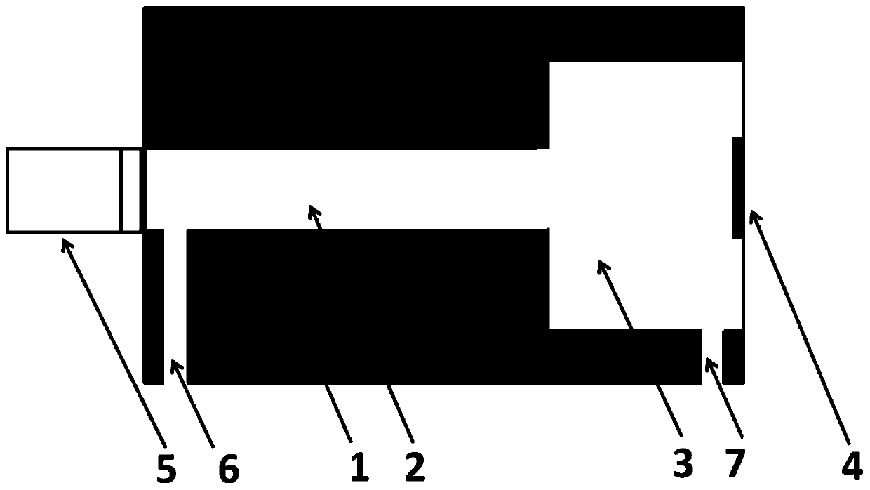
[0015] The present invention provides such figure 1 The semi-open cavity resonant photoacoustic cell shown includes a housing 1 , a resonant cavity 2 , a buffer chamber 3 , an optical glass window 4 , an acoustic wave sensor 5 , an air inlet 6 and an air outlet 7 . The acoustic wave sensor 5 collects the generated photoacoustic signal, and the concentration information of the gas to be measured can be obtained through analysis and processing. An optical glass window 4 is installed on the end face of the buffer chamber 3 to allow the excitation light to pass through smoothly. An air inlet 6 is provided at the position near the resonant cavity 2 of the acoustic wave sensor 5, and an air outlet 7 is provided on the side wall of the buffer chamber 3. .

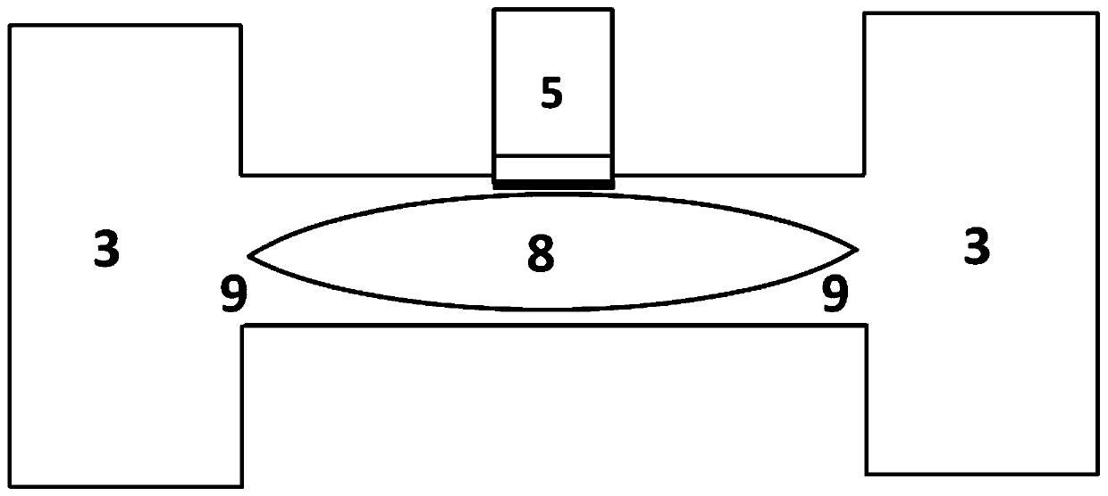
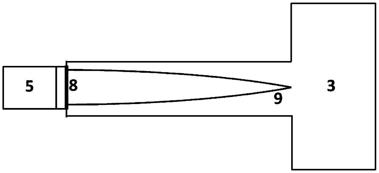
[0016] figure 2 The distribution of sound waves insid...


PUM


Abstract

The invention belongs to the technical field of the detection of trace gas and provides a half-open resonance type photoacoustic cell. The photoacoustic cell comprises a shell, a resonant cavity, a buffer chamber, optical glass window pieces, an acoustic wave sensor, an air inlet and an air outlet. According to the half-open resonance type photoacoustic cell, a buffer chamber on one side of a traditional first-order longitudinal resonance type photoacoustic cell resonant cavity is removed, the acoustic wave sensor is mounted at the place, a buffer chamber on the other side is preserved, and then a half-open photoacoustic cell structure is formed. The acoustic wave sensor is used for collecting sound signals and acquiring concentration information of to-be-tested gas through analytical processing. The optical glass window pieces are mounted on the end surfaces of the buffer chambers and permit excitation light to smoothly pass through, the air inlet is formed in the resonant cavity close to the acoustic wave sensor, and the air outlet is formed in the side wall of the buffer chamber. By utilizing the photoacoustic cell, the photoacoustic signal strength is increased, and the detection limit sensitivity of gas is relatively high; and meanwhile, the processing difficulty of the photoacoustic cell, the balanced time of gas and the volume of gas are reduced, and a new solution scheme is provided for the detection of high-sensitivity trace gas.

Description

technical field [0001] The invention belongs to the technical field of trace gas detection and relates to a semi-open cavity resonant photoacoustic cell. Background technique [0002] Trace gas detection has a wide range of application requirements in the fields of atmospheric environment detection, industrial process control and life sciences. With the development of laser technology, spectroscopic technology has become a gas detection method with the advantages of high sensitivity, fast response time and strong selectivity. Photoacoustic spectroscopy is a spectral calorimetry technique that directly measures the heat generated by a gas due to the absorption of light energy. It is a background-free absorption spectroscopy technique. The basic principle of gas photoacoustic spectroscopy is: after the gas to be measured absorbs light energy in a special band, the gas molecules transition from the ground state to the excited state, but due to the instability of the excited st...

Claims


Application Information

Patent Timeline
Patent Type & Authority Patents(China)
IPC IPC(8): G01N21/03G01N21/17G01N21/31
CPCG01N21/031G01N21/1702G01N21/31G01N2021/0314G01N2021/1704G01N2021/3125
Inventor 宫振峰陈珂于清旭
Owner DALIAN UNIV OF TECH
Why Eureka
Try Eureka