Dialysis cell for sample preparation for a chemical analysis method

a technology of dialysis cell and chemical analysis method, which is applied in the field of dialysis cell for sample preparation for chemical analysis to achieve the effects of improving the removal of analyte(s), shortening the equilibration time, and improving the removal ra

Active Publication Date: 2020-07-09
METROHM AG
View PDF1 Cites 1 Cited by
  • Summary
  • Abstract
  • Description
  • Claims
  • Application Information

AI Technical Summary

Benefits of technology

[0011]It is therefore an object of the present invention to overcome the abovementioned disadvantages in the prior art. More particularly, it is an object of the present invention to shorten the equilibration time to and to thus achieve an altogether higher sample throughput. Furthermore, the problem addressed by the present invention is that of achieving a better removal of the analyte(s) from the matrix in the case of heavily contaminated samples. Moreover, it is an object of the present invention to provide a device and a method for sample preparation by means of dialysis, by means of which a reliable and precise equilibration within a controllable equilibration time to is made possible.
[0012]These objects are achieved by a dialysis cell for sample preparation for a chemical analytical method, especially for ion chromatography, having the features in claim 1. The dialysis cell comprises a donor channel and a parallelly running acceptor channel. The donor channel and the acceptor channel are separated from one another by a selectively permeable dialysis membrane when used as intended. This means that, in particular, an analyte dissolved in a donor solution in the donor channel can get into the acceptor solution in the acceptor channel through the dialysis membrane. The acceptor channel has, at least sectionally, a volume VA which is smaller than a parallelly running volume VD of the donor channel.
[0013]It has been found that such an asymmetrical structure of the dialysis cell can markedly lower the equilibration times tA. This leads to shorter dialysis times tD and thus to an altogether higher sample throughput, and this is associated with a distinct saving of time and costs. Furthermore, shorter dialysis times tD reduce the period of time during which the dialysis membrane is in contact with the sample matrix. As a result, the breakthrough of matrix impurities can be significantly reduced. Moreover, the dialysis can be carried out with a distinctly smaller sample volume.
[0014]The dialysis cell according to the invention comprises two half-cells, between which the selectively permeable dialysis membrane is arranged. The donor channel and the acceptor channel are formed as, in each case, an indentation in a contact surface of one of the half-cells with the dialysis membrane. This structure of the dialysis cell has proved to be particularly robust, cost-effective in manufacturing and user-friendly with respect to operation and maintenance.
[0015]Moreover, the volumes of both half-cells are known and constant in the case of such a structure. By suitably choosing the amount / flow rate of the supplied and removed donor liquid or acceptor liquid, it is possible to avoid a positive pressure or negative pressure in one of the half-cells. Such a positive pressure or negative pressure leads to filtration, which can have an interfering effect on the concentration equilibrium of the analytes in the donor solution and acceptor solution that is reached as a consequence of diffusion. For example, filtrate can pass over into the acceptor channel in the case of a positive pressure in the donor channel.
[0016]The pressure-free dialysis, i.e., the dialysis in the absence of a pressure gradient within the dialysis cell, proves advantageous especially when donor liquids based on changing media or matrices are to be subjected to the dialysis. In the case of an unchanging matrix, as exists in the dialysis and / or analysis of blood serum in medical applications for example, the flow rate and thus the pressure can be appropriately adjusted on the basis of empirical values with corresponding effort, without the precision of the analytical values being excessively compromised as a result. In the case of changing matrices, as frequently occur in ion analysis by contrast, a pressure difference leads to uncontrollable and unpredictable dialysis times or equilibration times.

Problems solved by technology

This leads to shorter dialysis times tD and thus to an altogether higher sample throughput, and this is associated with a distinct saving of time and costs.

Method used


Image

  • Dialysis cell for sample preparation for a chemical analysis method
  • Dialysis cell for sample preparation for a chemical analysis method
  • Dialysis cell for sample preparation for a chemical analysis method

Examples


Embodiment Construction

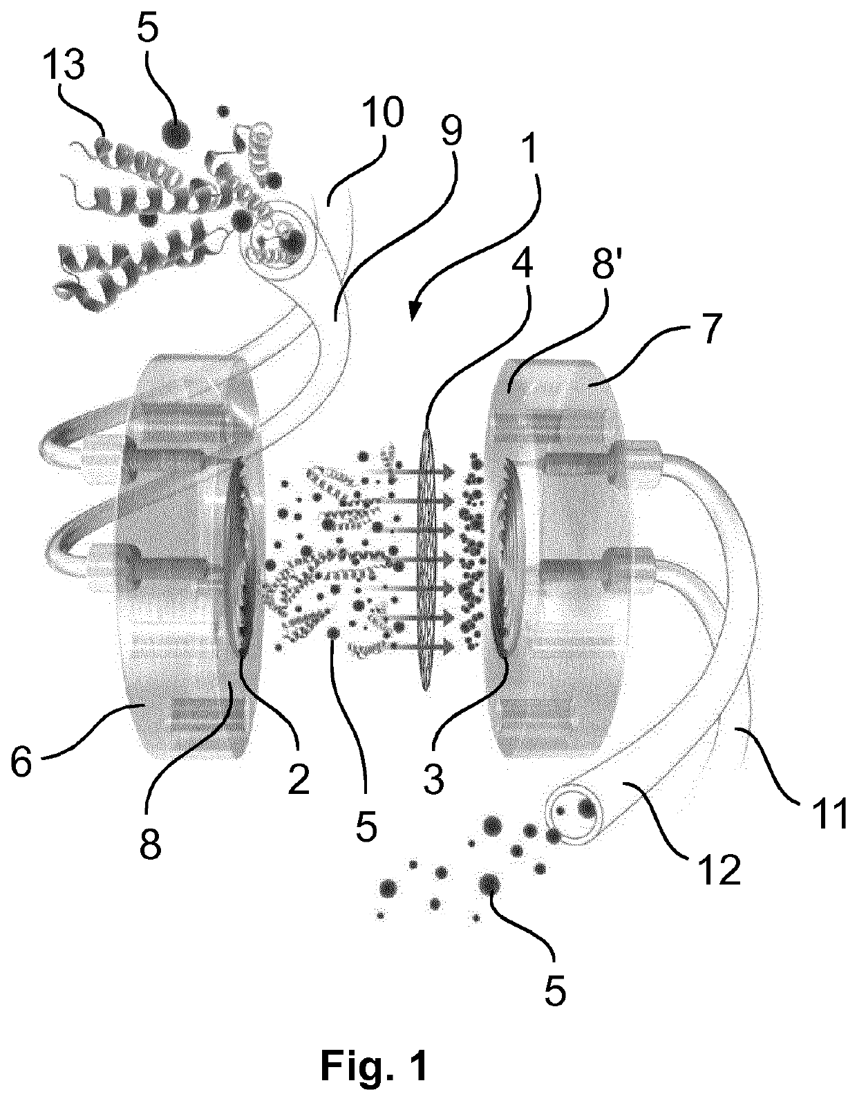
[0066]As is evident from FIG. 1, one embodiment of a dialysis cell 1 according to the invention consists of two half-cells 6 and 7, between which a selectively permeable dialysis membrane 4 is arranged. On their contact surfaces 8, 8′ with the dialysis membrane 4, the half-cells 6 and 7 each have a spiral indentation which forms the donor channel 2 and the acceptor channel 3, respectively. The donor channel 2 is connected to a supply line 9, via which a sample can be supplied. Furthermore, the donor channel 2 is connected to a discharge line 10, by means of which the sample can be discharged after passing through the dialysis cell 1 and can be supplied usually to a disposal point 17. The acceptor channel 3 as well is connected to a supply line 11 and a discharge line 12. The supply line 11 and the discharge line 12 of the acceptor channel 3 can be united to form an acceptor circuit. The sample solution conducted through the donor channel 2 contains at least one analyte, which is dep...


PUM

PropertyMeasurementUnit
pore sizeaaaaaaaaaa
diameteraaaaaaaaaa
lengthaaaaaaaaaa

Abstract

The invention relates to a dialysis cell for sample preparation for a chemical analysis method, in particular for ion chromatography. The dialysis cell comprises a donor channel and an acceptor channel extending parallel thereto. The donor channel and the acceptor channel are separated from each other by a selectively permeable dialysis membrane. In particular, an analyte that is dissolved in a donor solution in the donor channel can enter through the dialysis membrane into the acceptor solution in the acceptor channel. The acceptor channel has at least in some sections a volume that is smaller than the volume of the donor channel extending parallel thereto. Acceptor and donor channels are formed from half-cells, between which the dialysis membrane is arranged, wherein the donor channel and the acceptor channel are designed in each case as a recess in a contact surface of one of the half-cells with the dialysis membrane.

Description

[0001]This application is a National Stage completion of PCT / EP2018 / 071821 filed Aug. 10, 2018, which claims priority from European patent application serial no. 17185845.9 filed Aug. 11, 2017.FIELD OF THE INVENTION[0002]The present invention relates to a dialysis cell for sample preparation for a chemical analytical, to a device for sample preparation, to the use of a dialysis cell and to the use of a membrane as dialysis membrane in such a dialysis cell. The present invention further relates to an analytical system comprising a dialysis cell.BACKGROUND OF THE INVENTION[0003]In many chemical analytical methods, it is necessary to subject a sample to a preparation procedure before an actual analysis can be carried out. For example, samples for analysis by means of ion chromatography frequently contain matrix constituents, which are corrosive or can lead to precipitates, in addition to the ions to be analyzed, the analyte(s). Said matrix constituents sometimes make the analysis diffi...

Claims


Application Information

Patent Timeline
Patent Type & Authority Applications(United States)
IPC IPC(8): B01D61/24B01D61/28B01D63/08B01D71/14B01D71/34B01D71/50G01N1/34G01N30/14
CPCB01D63/087G01N1/34B01D61/243B01D61/28B01D71/50B01D71/34B01D2313/30G01N2030/146G01N2001/4016G01N30/14G01N2030/027B01D2311/26B01D2313/28B01D71/14G01N30/96B01D2311/2697A61M1/16A61M1/14
Inventor LÄUBLI, MARKUSFRENZEL, WOLFGANGMARKEVICIUTE, INGAABDERHALDEN, DANIEL
Owner METROHM AG
Why Eureka
Try Eureka