Method of producing periodic polarization inversion structures
a technology of inversion structure and periodic polarization, which is applied in the direction of polycrystalline material growth, single crystal growth, after-treatment, etc., can solve the problems of limiting the improvement of the density reducing the conversion efficiency, and reducing so as to reduce the period of the periodic polarization inversion structure and improve the productivity of the periodic polarization inversion parts. , the effect o
- Summary
- Abstract
- Description
- Claims
- Application Information
AI Technical Summary
Benefits of technology
Problems solved by technology
Method used
Image
Examples
##ventive example 1
Inventive Example 1
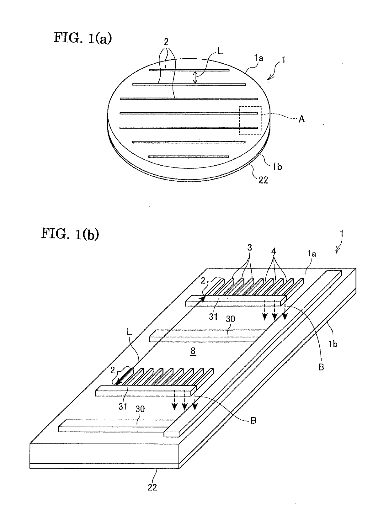
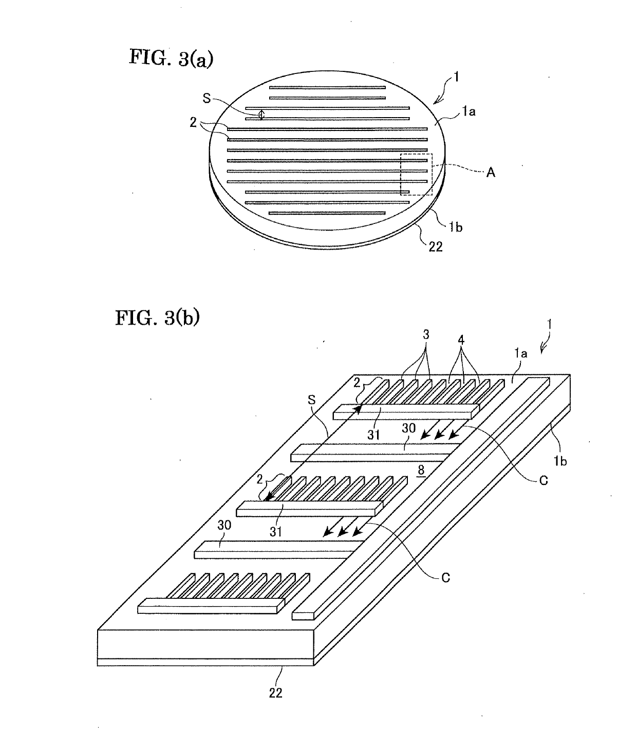
[0083]The periodic polarization inversion structures were formed according to the similar procedure as the comparative example 1. However, according to the present example, as shown in FIGS. 4 and 5, the first electrode piece part-arrays 2A and second electrode piece arrays 2B were provided separately to separately form the first periodic polarization inversion structures 5A and second periodic polarization inversion structures 5B. The period L of the first electrode piece part-arrays 2A was made 0.8 mm, and the period S of the first periodic polarization inversion structures and second electrode piece part-arrays was made 0.4 mm. The other procedural steps were same as those in the comparative example 1.
[0084]As a result, as shown FIG. 13, it was successfully formed good periodic polarization inversion structures each having a length of about 60 μm at small interval (note that an arrow has a length of about 60 μm). However, as shown in FIG. 14, the damages 12 wer...
##ventive example 2
Inventive Example 2
[0085]The periodic polarization inversion structures were formed as the similar procedure as the inventive example 1. However, according to the present example, the period L of the first electrode piece part-arrays was made 1.2 mm, and the period S of the first periodic polarization inversion structures and second electrode piece part-arrays was made 0.6 mm. The density of the periodic polarization inversion structures was lowered at some extent.
[0086]As a result, it was successfully formed good first periodic polarization inversion structures and second polarization inversion structures each having a length of about 50 μm. Further, it could be successfully formed at a narrow interval. However, as shown in FIG. 15, the damages 12 were occasionally observed (refer to FIG. 6(b)) due to concentration of electric field between the ends of a part of the electrode piece part-arrays and ends of the first periodic polarization inversion structures, when the voltage was ap...
##ventive example 3
Inventive Example 3
[0087]The electrode piece arrays were formed as those in the inventive example 1 and it was tried to form the periodic polarization inversion structures. However, according to the present example, as shown in FIG. 8, the ends 5e of the first periodic polarization inversion structures 5A were set apart from the electrode piece part-arrays 2C, by a distance of 2 mm (t) in the lengthwise direction P of the first electrode piece part-arrays 2C.
[0088]As a result, as shown in FIG. 16, it was successfully formed good periodic polarization inversion structures each having a length of about 60 μm at a narrow interval (note that an arrow has a length of 60 μm). Further, as shown in FIG. 17, it was not observed the damages 12 due to concentration of electric field between the ends of a part of the electrode piece part-arrays and ends of the first polarization inversion structures, when the voltage is applied on the second electrode piece part-arrays.
PUM
| Property | Measurement | Unit |
|---|---|---|
| off-cut angle | aaaaa | aaaaa |
| off-cut angle | aaaaa | aaaaa |
| thickness | aaaaa | aaaaa |
Abstract
Description
Claims
Application Information
 - R&D
- Intellectual Property
- Life Sciences
- Materials
- Tech Scout
- Unparalleled Data Quality
- Higher Quality Content
- 60% Fewer Hallucinations
Browse by: Latest US Patents, China's latest patents, Technical Efficacy Thesaurus, Application Domain, Technology Topic, Popular Technical Reports.
© 2025 PatSnap. All rights reserved.Legal|Privacy policy|Modern Slavery Act Transparency Statement|Sitemap|About US| Contact US: help@patsnap.com


