Device For Reducing Pressure Surge

a technology for reducing pressure surge and devices, applied in the direction of pipe/joint/fittings, service pipe systems, construction, etc., can solve the problems of significant increase in the risk of failure of devices connected to the network, disturbing noise even at locations and levels, and disadvantageous production of pressure surge, etc., to reduce fluid hammer, reduce pressure surge, and withstand

Inactive Publication Date: 2019-09-19
EROS GYULA +2
View PDF0 Cites 4 Cited by
  • Summary
  • Abstract
  • Description
  • Claims
  • Application Information

AI Technical Summary

Benefits of technology

[0011]The primary object of the invention is to provide a device for reducing pressure surge, which is free of disadvantages of prior art approaches to the greatest possible extent.
[0012]The object of the invention is to provide a device for reducing pressure surge that is capable of performing its function long lasting, with an enduring effectiveness. A further object is to provide a device wherein the sealing members isolating the gas space are subjected to the lowest load possible, preferably to provide a device wherein the inherent leakage of the sealing members does not pose a problem for the operation of the device for reducing fluid hammer.
[0013]By means of the device according to the invention for reducing pressure surge, particularly for reducing or damping the shock wave accompanying the pressure surge event the above objects can be achieved and the disadvantages of known approaches can be eliminated.
[0016]The application of the device for reducing pressure surge according to the invention provides the advantage that it is not required to modify or adapt existing appliances (consumers); in an embodiment, the device according to the invention has to be connected in series into the fluid system (i.e. has to be inserted into the pipe carrying the fluid flow) subjected to a danger of pressure surge; due to the inclusion (insertion) of the device fluid hammer can be reduced significantly. Some embodiments of the device according to the invention are to be connected to the fluid system in parallel (via a single connection, in which case the device is inserted into the system by means of a T- or Y-member, or is connected to an end point of the network), the efficiency of parallel-connected devices can be slightly lower relative to series-connected devices.

Problems solved by technology

A pressure surge is disadvantageously produced—especially at relatively higher network pressures—when certain tap cartridge types, e.g. ceramic-cartouche universal single-lever mixer tap cartridges are turned off with a sudden movement, which places a technical load not only on the given tap cartridge but also on the pipe network, and significantly increases the risk of failure for devices connected to the network.
In addition to the above mentioned problems fluid hammer may cause oscillations in the pipe system of the fluid network, which—especially with lightweight-construction walls—may result in disturbing noise even at locations and levels significantly further away from the given consumer.
The drawback of this known solution is that as a result of the fluid hammer events pressure in the already highly pressurized gas space increases further, and thus the seals of the gas space (which isolate the gas space from the fluid space) are subjected to high stresses.
This results in that the device for reducing pressure surge according to the document is worn over time and its efficiency is reduced (compared to its original condition, i.e. it can no longer suppress pressure surge to the original extent by the reduction of the pressure of the gas space, and is no longer capable of leading back the piston after the pressure rise accompanying the pressure surge is over, it may even happen over time that the piston can no longer assume its base position).
Accordingly, the back-and-forth flow between the gas space and the outside space is uncontrolled.

Method used


Image

  • Device For Reducing Pressure Surge
  • Device For Reducing Pressure Surge
  • Device For Reducing Pressure Surge

Examples


Embodiment Construction

[0011]The primary object of the invention is to provide a device for reducing pressure surge, which is free of disadvantages of prior art approaches to the greatest possible extent.

[0012]The object of the invention is to provide a device for reducing pressure surge that is capable of performing its function long lasting, with an enduring effectiveness. A further object is to provide a device wherein the sealing members isolating the gas space are subjected to the lowest load possible, preferably to provide a device wherein the inherent leakage of the sealing members does not pose a problem for the operation of the device for reducing fluid hammer.

[0013]By means of the device according to the invention for reducing pressure surge, particularly for reducing or damping the shock wave accompanying the pressure surge event the above objects can be achieved and the disadvantages of known approaches can be eliminated.

[0014]The device for reducing pressure surge according to the invention (...


PUM


Abstract

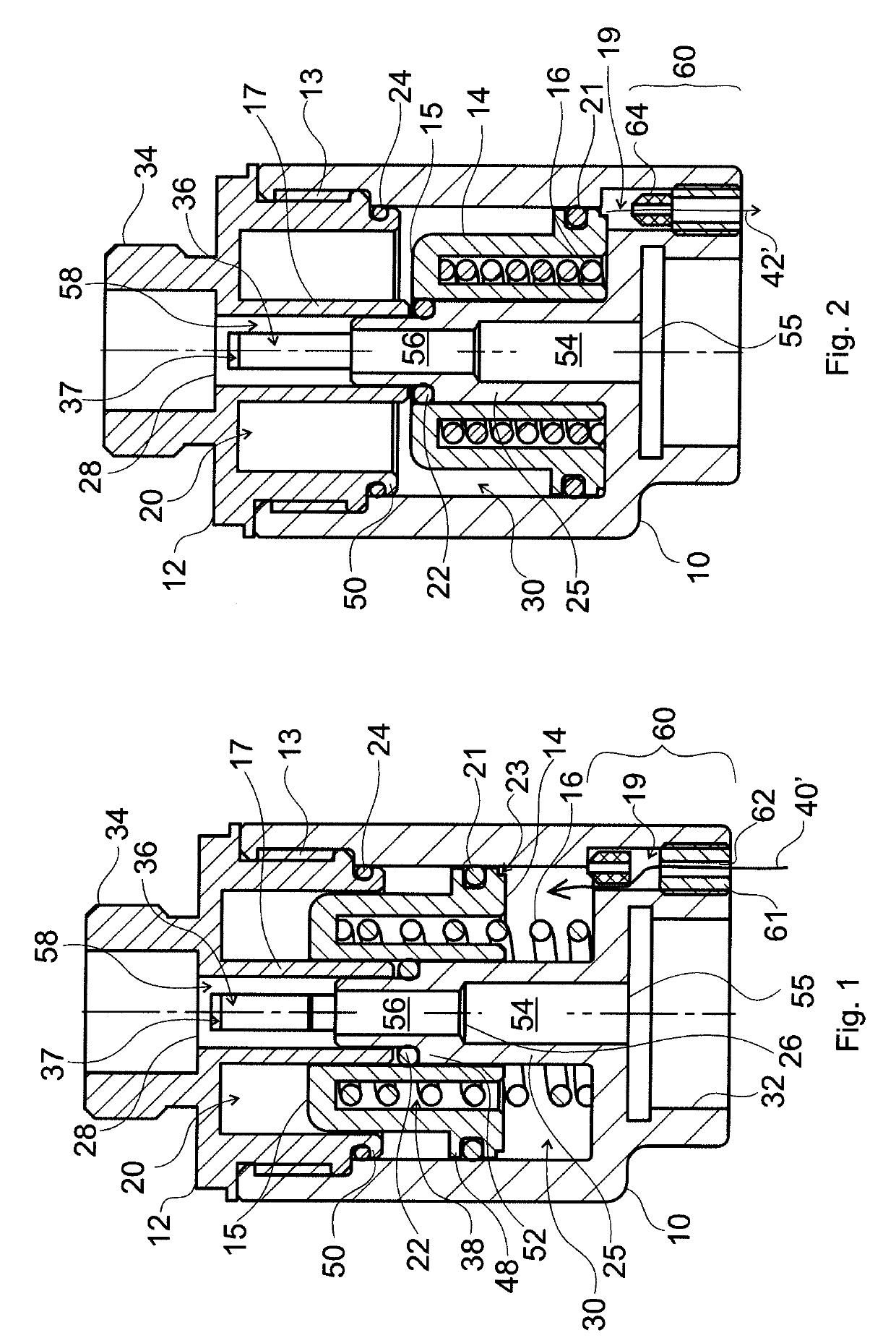
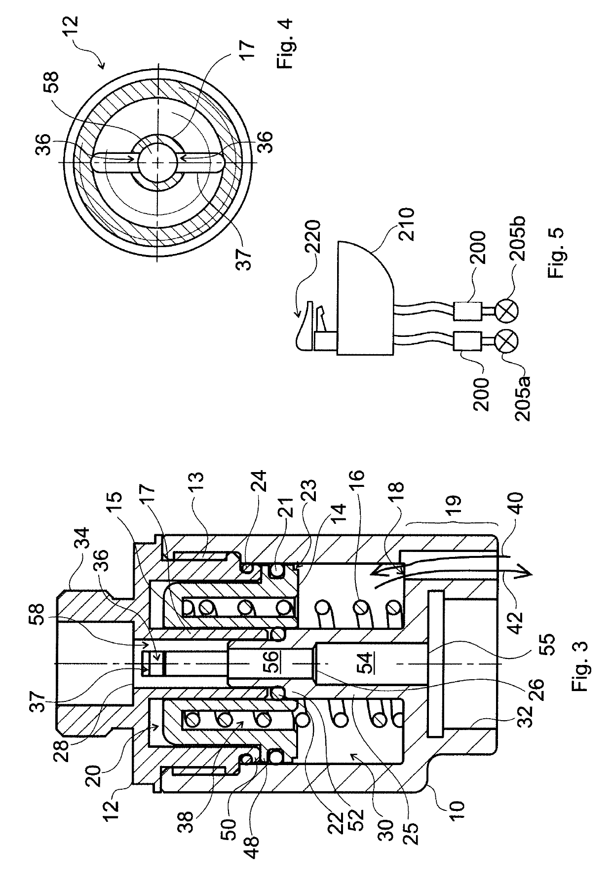
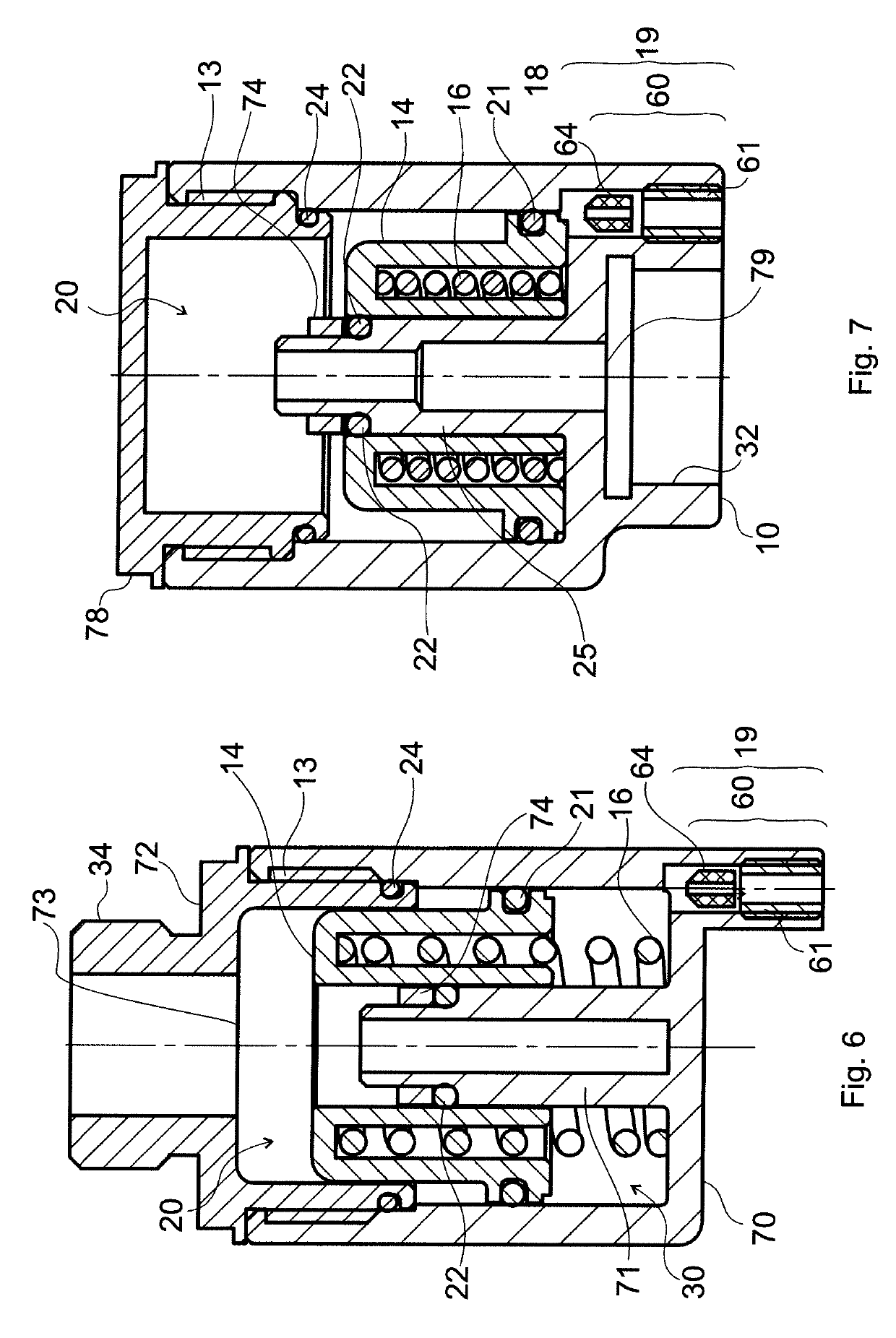
The invention is a device for reducing pressure surge, comprising a container having an inner space which container has a connection opening (28) for connecting a pipe member being suitable for flowing fluid, a piston member (14) dividing the inner space of the container into a fluid space (20) being in fluid flow connection with the connection opening (28) and a gas space (30), and being movable along a piston displacement axis, an elastic element being arranged in the gas space (30), being supported against the piston member (14) and undergoing elastic deformation in case the piston member (14) is displaced along the piston displacement axis, and a throttle valve (60) being in fluid flow connection with the gas space (30) at any position of the piston member (14), being arranged to connect the gas space (30) and the space surrounding the container, and allowing a continuous gas flow in both directions.

Description

TECHNICAL FIELD[0001]The invention relates to a device adapted for reducing (managing) pressure surge (pressure blow, especially, network or closure pressure surge, e.g. water hammer). Network pressure surge is essentially a shock wave produced for some reason, especially by an abrupt interruption of flow somewhere in a network carrying a fluid (a liquid or gaseous material), generated by the inertia of the accelerated fluid (a load produced by pressure surge generated by other devices in the network) which travels through at least a part of the fluid network. A shock wave accompanies also closure (closing) pressure surge that can be produced by (abruptly) interrupting consumption flow at a given point of consumption in a fluid network, e.g. by turning off a tap, this phenomenon therefore corresponds to a given appliance. Network- and closure pressure surges are therefore related phenomena as both are associated with an abrupt closure. They can be differentiated by whether the effec...

Claims


Application Information

Patent Timeline
Patent Type & Authority Applications(United States)
IPC IPC(8): F16L55/053
CPCF16L55/053E03B7/075F16L55/055F16L55/045
Inventor EROS, GYULABEREZNAI, DORABEREZNAI, JOZSEF
Owner EROS GYULA
Why Eureka
Try Eureka