Method and Device for Multi-Antenna Transmission in UE and Base Station

Active Publication Date: 2019-09-19
APEX BEAM TECH LLC
View PDF4 Cites 7 Cited by
  • Summary
  • Abstract
  • Description
  • Claims
  • Application Information

AI Technical Summary

Benefits of technology

The patent describes a method that allows a device to quickly determine the location of a specific resource pool of time in a multi-antenna system. This is accomplished by associating the resource pool with a specific antenna port group. Additionally, the patent also discusses the use of virtualization vectors to reduce the cost of RF for multi-antenna systems. Overall, the technical effects of this patent are improved speed and accuracy in identifying specific resource pools and reduced RF costs.

Problems solved by technology

However, an increase in the number of cell users will lead to a large amount of signaling overhead for dynamic scheduling of wireless time-frequency resources.
The signaling overhead of wireless resource dynamic scheduling is an urgent problem to be solved in massive MIMO system.

Method used


Image

  • Method and Device for Multi-Antenna Transmission in UE and Base Station
  • Method and Device for Multi-Antenna Transmission in UE and Base Station
  • Method and Device for Multi-Antenna Transmission in UE and Base Station

Examples


embodiment 1

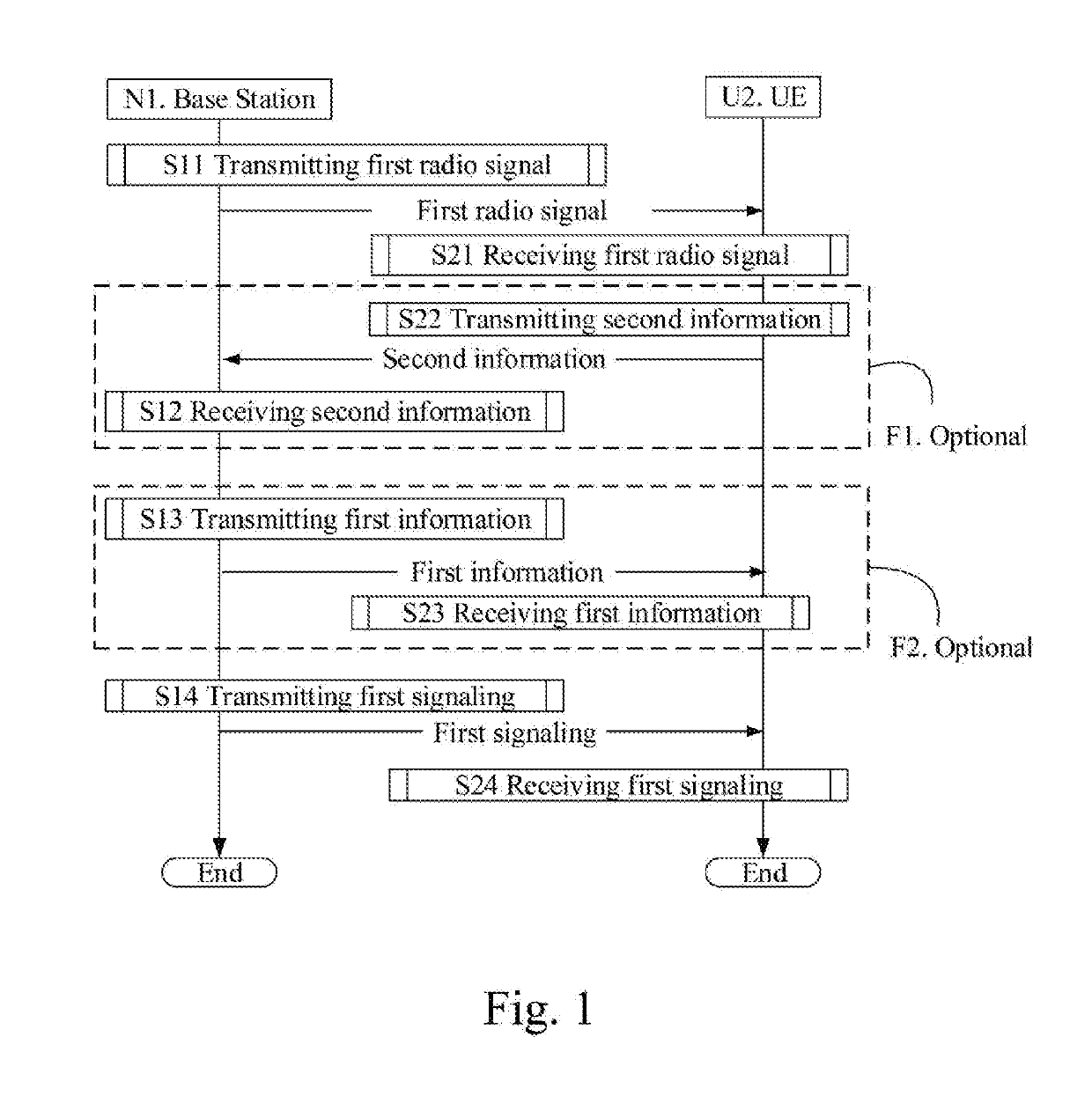
[0275]Embodiment 1 illustrates a flow chart of wireless transmission according to one embodiment of the present disclosure, as shown in FIG. 1. In FIG. 1, the base station N1 is a maintenance base station of the serving cell of the UE U2. In the figure, the step in the box identified as F1 and F2 are optional, respectively.

[0276]The base station N1 transmits the first radio signal in step S11; receives the second information in step S12; transmits the first information in step S13; and transmits the first signaling in step S14.

[0277]The UE U2 receives the first radio signal in step S21; transmits the second information in step S22; receives the first information in step S23; and receives the first signaling in step S24.

[0278]In Embodiment 1, the first radio signal is transmitted by K antenna port groups, the antenna port group(s) includes a positive integer number of the antenna port(s); a first antenna port group is one of the K antenna port groups; the first signaling is used to d...

embodiment 2

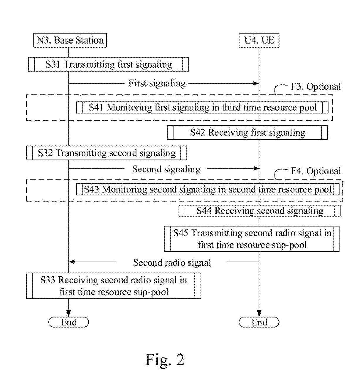
[0285]Embodiment 2 illustrates a flowchart of wireless transmission according to another one embodiment of the present disclosure, as shown in FIG. 2. In FIG. 2, the base station N3 is a maintenance base station of the serving cell of the user equipment U4. In Embodiment II, the N3 can reuse steps S11-S13 in FIG. 1 before step 31; the U4 can reuse steps S21-S23 in FIG. 1 before step S41. In FIG. 2, the step in the box identified as F3 and F4 are optional, respectively.

[0286]The base station N3 transmits a first signaling in step S31; transmits a second signaling in step S32; receives second radio signal in the first time resource sub-pool in step S33.

[0287]The UE U4 monitors a first signaling in the third time resource pool in step S41; receives the first signaling in step S42; monitors a second signaling in the second time resource pool in step S43; receives the second signaling in step S44; transmits the second radio signal in the first time resource sub-pool in step S45.

[0288]In ...

embodiment 3

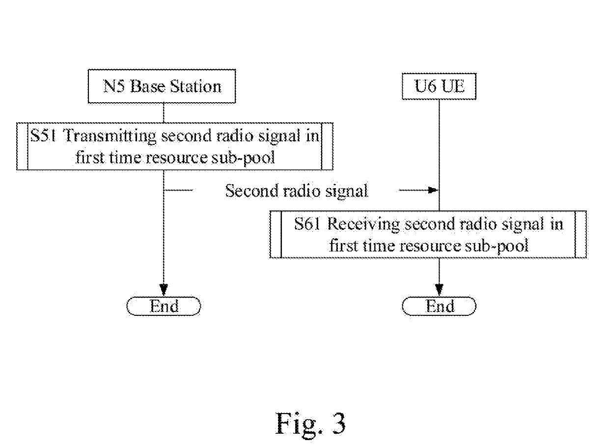
[0294]Embodiment 3 illustrates a flowchart of wireless transmission in accordance with yet another embodiment of the present disclosure, as shown in FIG. 3. In FIG. 3, a base station N5 is a maintenance base station for a serving cell of the UE U6. In Embodiment 3, the N5 can reuse steps S11-S13 in FIG. 1 and steps S31-S32 in FIG. 2 prior to step 51; the U4 can reuse steps S21-S23 in FIG. 1 and steps S41-S44 before in FIG. 2 prior to step S61.

[0295]The base station N5 transmits the second radio signal in the first time resource sub-pool in step S51.

[0296]The UE U6 receives the second radio signal in the first time resource sup-pool in step S61.


PUM


Abstract

The present disclosure discloses a method and device for multi-antenna transmission in UE and base station. The user equipment first receives a first radio signal at first, then receives a first signaling. The first radio signal is transmitted by K antenna port groups, and the antenna port group includes a positive integer number of antenna port(s), and the first antenna port group is one of the K antenna port groups. The first signaling is used to determine a first time resource pool, at least one first antenna virtualization vector and the second antenna virtualization vector is associated with the first antenna port group. The invention effectively reduces signaling overhead of wireless resource dynamic scheduling of a massive MIMO system.

Description

CROSS-REFERENCE TO RELATED APPLICATION[0001]This application is a continuation of International Application No. PCT / CN2017 / 112033, filed on Nov. 21, 2017, claiming the priority benefit of Chinese Patent Application Serial Number 201611098328.7, filed on Dec. 3, 2016. The afore-mentioned patent applications are hereby incorporated by reference in their entireties.BACKGROUNDTechnical Field[0002]The present disclosure relates to a multiple antenna transmission method in a wireless communication system.Related Art[0003]Massive Multiple-Input Multiple-Output (MIMO) has become a research hotspot for next-generation mobile communications. In massive MIMO, multiple antennas can improve communication quality by forming narrower beams pointing to a specific direction through beamforming.[0004]According to the discussion of 3rd Generation Partner Project (3GPP) Radio Access Network (RAN), the hybrid beamforming combining analog beamforming and digital beamforming has become an important resear...

Claims


Application Information

Patent Timeline
IPC IPC(8): H04L5/00H04B7/0413H04L1/00H04L1/18H04B7/06H04W88/02
CPCH04W88/02H04L1/0003H04L5/0082H04B7/0617H04B7/0413H04L5/005H04L1/1819H04B7/0408H04L5/0023H04L5/0053H04B7/0456H04L5/0094H04B7/06H04L1/0025H04L1/1822
Inventor ZHANG, XIAOBO
Owner APEX BEAM TECH LLC
Why Eureka
Try Eureka