Carbon dioxide reduction apparatus and method of producing organic compound

a carbon dioxide reduction and organic compound technology, applied in the direction of electrolysis organic reduction, electrolysis components, cells, etc., can solve the problems of ineffective utilization of electrodes on the other side of the electrode, inability to effectively utilize electrodes, and inability to achieve the effect of effective electrical energy utilization

Active Publication Date: 2019-09-26
SEKISUI CHEM CO LTD
View PDF2 Cites 24 Cited by
  • Summary
  • Abstract
  • Description
  • Claims
  • Application Information

AI Technical Summary

Benefits of technology

[0012]Thus, an object of the present invention is to provide a carbon dioxide reduction apparatus that can effectively utilize electrical energy by combining a reaction occurring on a first electrode (cathode) with a reaction occurring on a second electrode (anode); and a method of producing an organic compound using the carbon dioxide reduction apparatus.

Problems solved by technology

As has been described above in each of the above described apparatuses, conventionally attention is often paid to any one of the reaction on the first electrode and the reaction on the second electrode, and the reaction on an electrode in the other side is not effectively utilized in many cases.
For instance, in the carbon dioxide reduction apparatus, an oxidation reaction of water is carried out on the second electrode in many cases, but oxygen which is the product by the oxidation reaction is not industrially valuable, and electrical energy required for the reaction on the second electrode of the carbon dioxide reduction apparatus results in being lost.

Method used


Image

  • Carbon dioxide reduction apparatus and method of producing organic compound
  • Carbon dioxide reduction apparatus and method of producing organic compound
  • Carbon dioxide reduction apparatus and method of producing organic compound

Examples


first embodiment

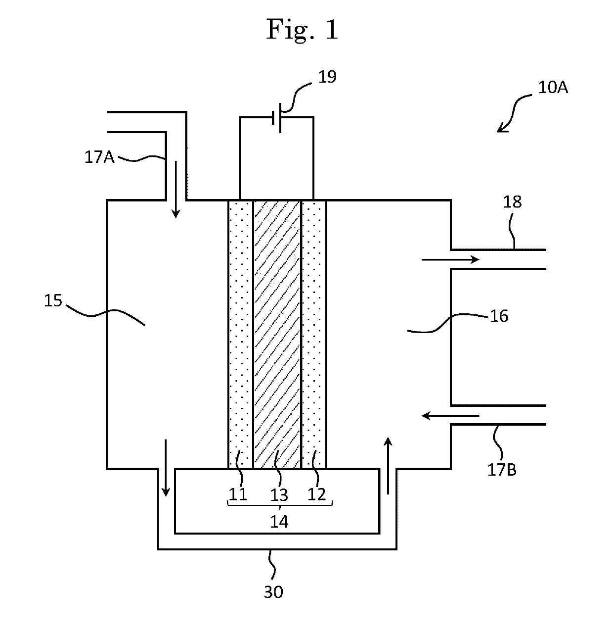
[0043]FIG. 1 is a schematic view of a carbon dioxide reduction apparatus 10A according to a first embodiment of the present invention. Incidentally, in each drawing, each arrow indicates a movement direction of the raw material and the product in the carbon dioxide reduction apparatus 10A.

[0044]The carbon dioxide reduction apparatus 10A has a first electrode 11, a second electrode 12 and an ion conducting membrane 13 provided inside a cell. The first electrode 11 and the second electrode 12 are arranged on both sides of the ion conducting membrane 13, respectively, and are bonded thereto so as to form a membrane-electrode assembly 14.

[0045]In the carbon dioxide reduction apparatus 10A, the cell is demarcated by the membrane-electrode assembly 14, so that a first electrochemical compartment 15 and a second electrochemical compartment 16 are formed. Thereby, the carbon dioxide reduction apparatus 10A has a two chamber type cell-structure in which the cell is separated into two chamber...

second embodiment

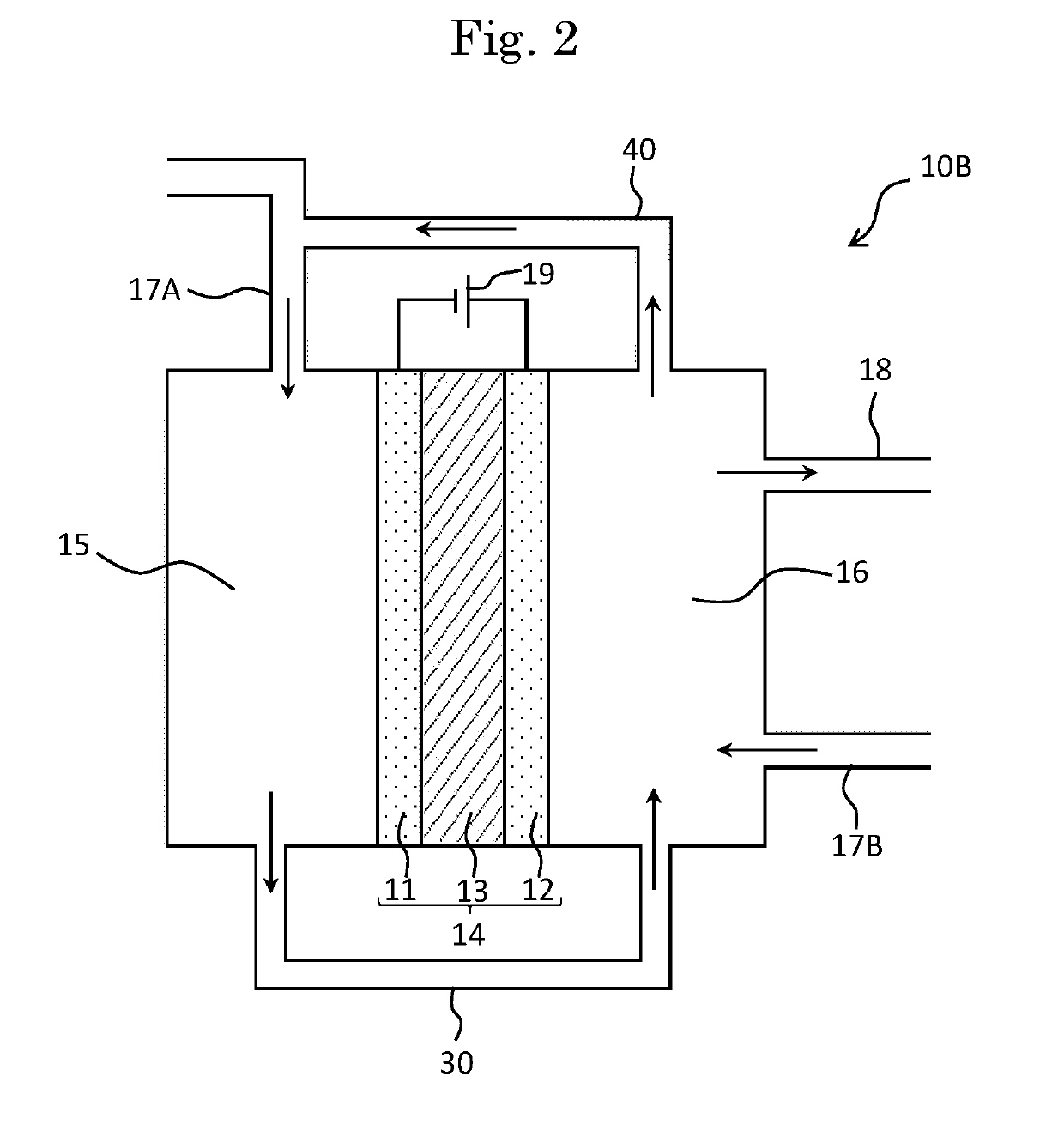
[0111]Next, a carbon dioxide reduction apparatus according to a second embodiment of the present invention will be described. The carbon dioxide reduction apparatus of the second embodiment comprises a second connecting path. FIG. 2 shows a schematic view of a carbon dioxide reduction apparatus 10B according to the second embodiment of the present invention.

[0112]The carbon dioxide reduction apparatus 10B has a similar configuration to that of the carbon dioxide reduction apparatus 10A of the first embodiment, except that the carbon dioxide reduction apparatus 10B further comprises a second connecting path 40 which connects the first electrochemical compartment 15 with the second electrochemical compartment 16. Incidentally, among each configuration which the carbon dioxide reduction apparatus 10B of the present embodiment has, the members denoted by the same reference numerals as those of the carbon dioxide reduction apparatus 10A of the first embodiment have similar configurations...

third embodiment

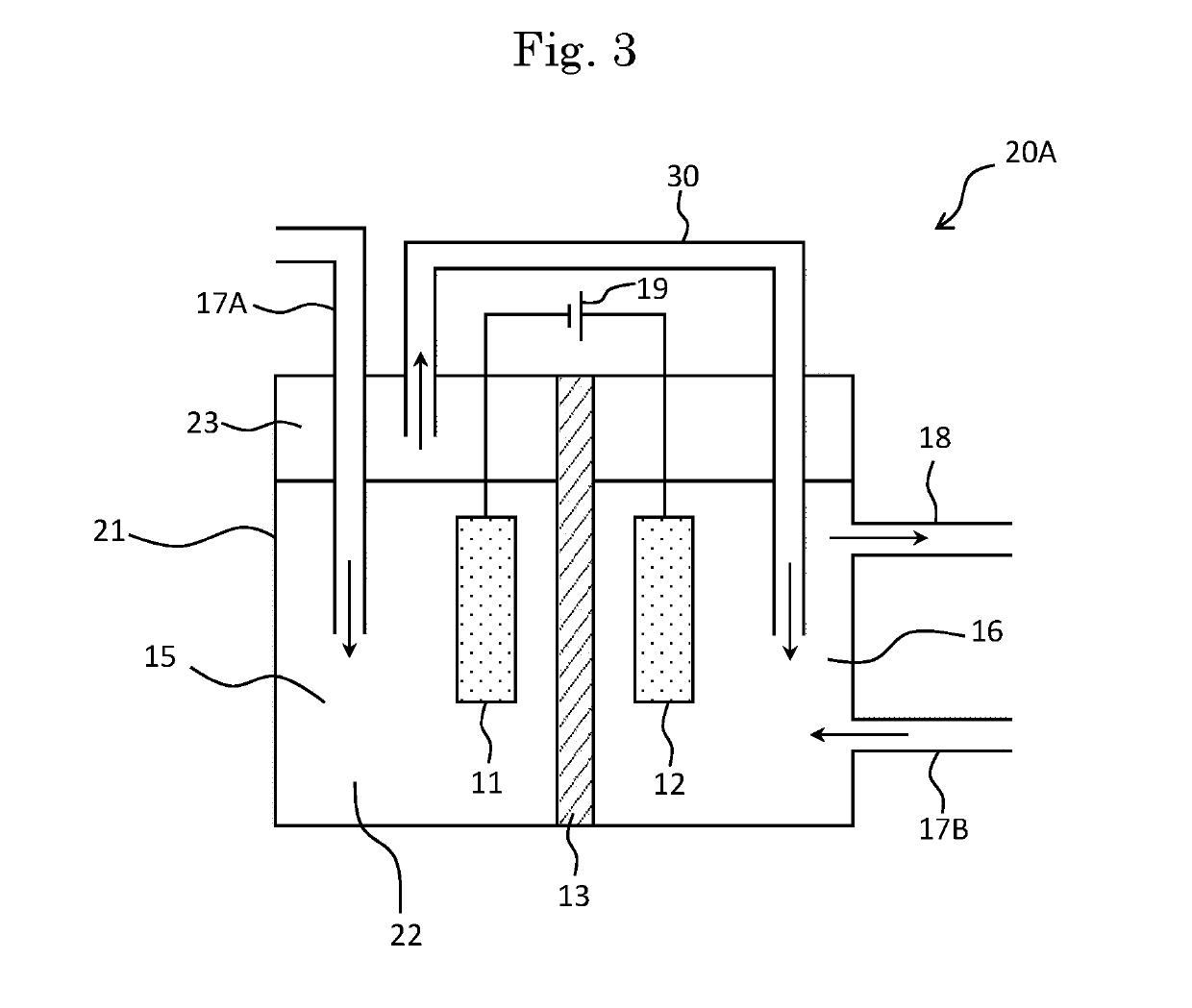
[0118]Next, a carbon dioxide reduction apparatus according to a third embodiment of the present invention will be described. The third embodiment is a carbon dioxide reduction apparatus in which a first electrochemical compartment 15 is filled with an electrolyte solution. FIG. 3 shows a schematic view of a carbon dioxide reduction apparatus 20A according to the third embodiment of the present invention. Incidentally, among each configuration which the carbon dioxide reduction apparatus 20A of the present embodiment has, the members denoted by the same reference numerals as those of the carbon dioxide reduction apparatus 10A of the first embodiment have similar configurations to those of the carbon dioxide reduction apparatus 10A, unless otherwise described.

[0119]In the carbon dioxide reduction apparatus 20A, the inside of an electrochemical cell 21 is filled with an electrolyte solution 22, and the first electrode 11 and the second electrode 12 are arranged in the inside of the ele...


PUM

PropertyMeasurementUnit
electrochemicalaaaaaaaaaa
electrical energyaaaaaaaaaa

Abstract

A carbon dioxide reduction apparatus comprises a first electrochemical compartment provided with a first electrode, a second electrochemical compartment provided with a second electrode, an ion conducting membrane which demarcates the first electrochemical compartment from the second electrochemical compartment, and a first connecting path which connects the first electrochemical compartment with the second electrochemical compartment. The first electrode contains a first catalyst which catalyzes a reduction of carbon dioxide to a reduced product, and the second electrode contains a second catalyst which catalyzes a reaction between the reduced product and a reactant. The first connecting path is a connecting path which allows the reduced product in the first electrochemical compartment to flow out to the second electrochemical compartment.

Description

TECHNICAL FIELD[0001]The present invention relates to a carbon dioxide reduction apparatus and a method of producing an organic compound.BACKGROUND ART[0002]A carbon dioxide reduction apparatus which electrically reduces carbon dioxide to produce valuable chemicals has attracted attention as a method for decreasing the amount of carbon dioxide emission and storing natural energy, and has been researched and developed (Non-Patent Literature 1). In a conventional carbon dioxide reduction apparatus, carbon dioxide is reduced on a first electrode (cathode) side; and metals, alloys, metal carbon compounds, carbon compounds and the like have been reported, as catalysts for high efficient reductions (Patent Literatures 1 to 3). In the carbon dioxide reduction apparatuses reported in each of the above literatures, efforts have been made on development of only the reaction on the first electrode (cathode), and conventionally, there have been few development examples in which attention has be...

Claims


Application Information

Patent Timeline
Patent Type & Authority Applications(United States)
IPC IPC(8): C25B9/08C25B3/04C25B15/08C25B3/25C25B3/23C25B9/19
CPCC25B3/04C25B9/08C25B15/08C25B1/00C25B3/23C25B9/23C25B9/19C25B3/25
Inventor FUJINUMA, NAOHIRO
Owner SEKISUI CHEM CO LTD
Why Eureka
Try Eureka