Complex surface three-coordinate measuring device and error compensation method

a three-coordinate measuring device and complex surface technology, applied in the field of three-dimensional measurement, can solve the problems of large change in the curvature of the workpiece profile, the accuracy requirements of workpieces are getting higher and higher, and the accuracy of existing three-coordinate measurement accuracy cannot meet the detection requirements of some high-precision parts, etc., to achieve the effect of improving the measurement accuracy, reducing vibration, and effectively measuring small displacemen

Active Publication Date: 2019-09-26
HUAZHONG UNIV OF SCI & TECH
View PDF0 Cites 8 Cited by
  • Summary
  • Abstract
  • Description
  • Claims
  • Application Information

AI Technical Summary

Benefits of technology

[0024]1. in the present invention, a three-coordinate measuring device in which a three-degree-of-freedom motion platform cooperates with a force control probe is designed, and through studying and designing the specific structure and arrangement of the force control probe to add a force control part in the three-coordinate measurement, the stylus is always kept in constant force contact with the workpiece surface during measurement, and the measured data can truly reflect the contour information of the workpiece surface;
[0025]2. in the present invention, a six-axle force sensor is used to collect the contact force received by the stylus, and the error compensation direction of the radius of the stylus spherical head is estimated by the force direction, improving the measurement accuracy;
[0026]3. in the present invention, a spring and a micro grating ruler are disposed in the force control probe, which can effectively reduce the vibration generated when the rigid body is in direct contact with other rigid body and can effectively measure the small displacement of the stylus which is in contact with the workpiece surface, so as to further ensure the measurement accuracy;
[0027]4. in the present invention, a column-type three-axis motion platform is used, which provides a spacious space for workpiece mounting and disassembly; and two guide rails are arranged in the XY directions, respectively, which improves the movement accuracy of the platform; and
[0028]5. in the present invention, an error compensation method based on force information is further provided, in which based on the data measured by the six-axle force sensor and the micro grating ruler, the three-dimensional measurement of the complex surface is realized, and the real-time compensation of the measurement data is realized during the measurement, thereby improving the measurement accuracy.

Problems solved by technology

However, with the continuous development of industrial technology, the accuracy requirements of workpieces are getting higher and higher, and the existing three-coordinate measurement accuracy can no longer meet the detection requirements of some high-precision parts.
Typical parts with complex surfaces such as aero-engine blades, steam turbine blades and gas turbine blades not only require high processing and inspection accuracy, but also have large change in the curvature of the workpiece profile.
In addition, large parts with complex surfaces such as automobile bodies, high-speed rail bodies and wind turbine blades have a large measurement area and large change in surface curvature.
Therefore, it is difficult for the conventional CMMs to accurately measure these parts.
Since the parts with complex surfaces have large change in surface curvature, the contact direction of the stylus with the workpiece surface is changed with the undulation of the surface, and the actual contact direction of the stylus with the workpiece surface cannot be accurately estimated by using the above two methods.
Thus, the approximate location of the actual contact point cannot be accurately calculated.

Method used


Image

  • Complex surface three-coordinate measuring device and error compensation method
  • Complex surface three-coordinate measuring device and error compensation method
  • Complex surface three-coordinate measuring device and error compensation method

Examples


Embodiment Construction

[0036]For clear understanding of the objectives, features and advantages of the present invention, detailed description of the present invention will be given below in conjunction with accompanying drawings and specific embodiments. It should be noted that the embodiments described herein are only meant to explain the present invention, and not to limit the scope of the present invention.

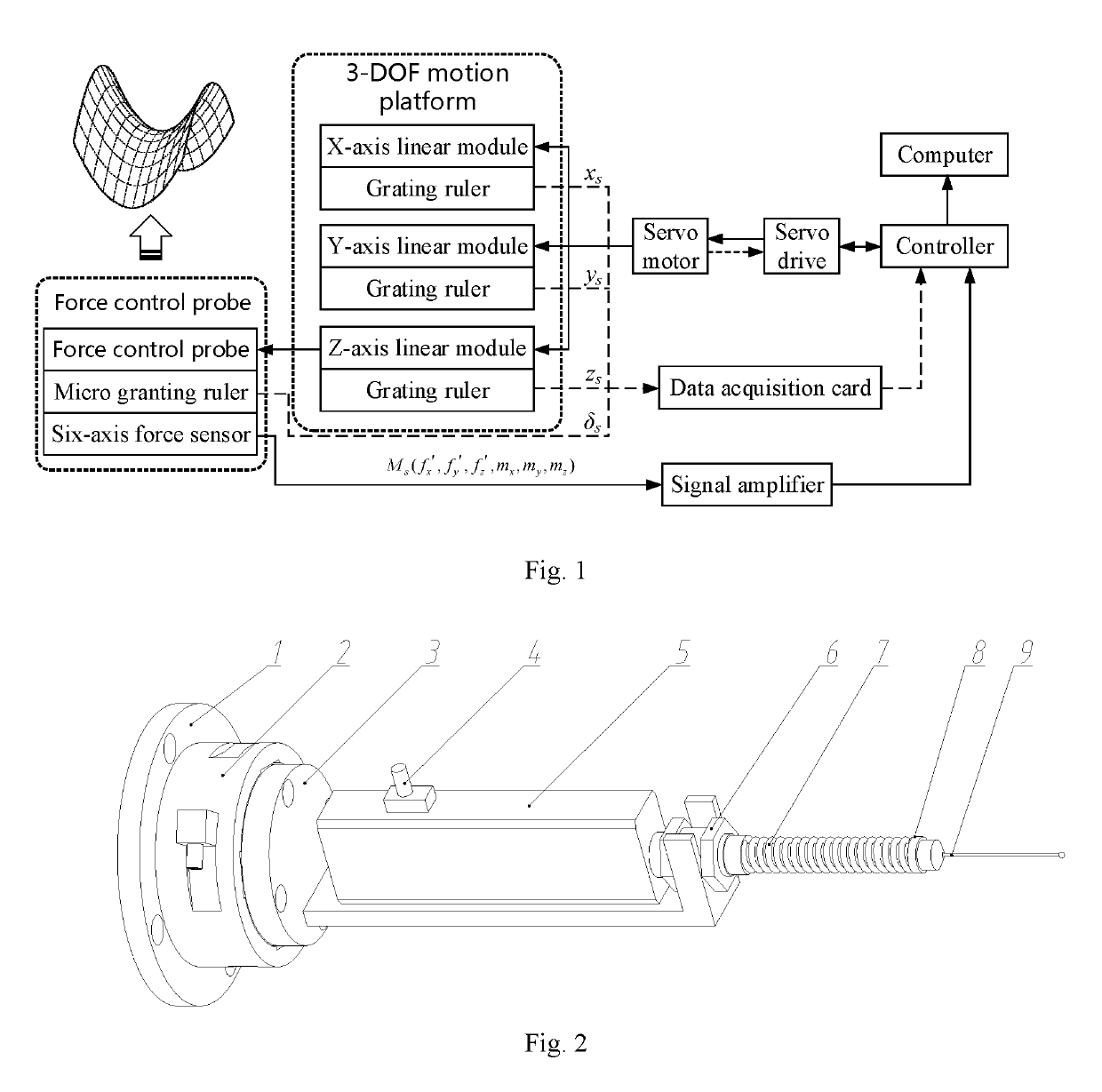
[0037]As shown in FIG. 1, a force control probe for three-coordinate measurement of a complex surface is provided in an embodiment of the present invention, in which the force control probe is in the same direction as the X axis of the three-degree-of-freedom motion platform, and is used for keeping the stylus in constant force contact with the workpiece surface and feeding back the contact force between the stylus and the workpiece surface through a six-axis force sensor. As shown in FIG. 2, the force control probe includes a flange 1, a six-axis force sensor 2 and a micro grating ruler. The flange...


PUM

PropertyMeasurementUnit
contact forceaaaaaaaaaa
forceaaaaaaaaaa
real-time coordinate Ptaaaaaaaaaa

Abstract

A complex surface three-coordinate measuring device includes a three-degree-of-freedom motion platform and a force control probe, the force control probe is fixedly mounted on the Z-axis sliding block, which is in the same direction as the X-axis direction and used to contact with the workpiece surface with constant force. A six-axis force sensor is used to collect the contact force between the stylus and the workpiece surface. In this method, the force control is realized in the measurement to make the stylus in constant force contact with the workpiece surface. The error compensation direction is determined according to the direction of the contact force, and then the effective radius of the stylus spherical head is compensated in this direction, thus the actual contact point of stylus and workpiece can be obtained.

Description

TECHNICAL FIELD[0001]The present invention belongs to the field of three-dimensional measurement, and more particularly relates to a complex surface three-coordinate measuring device and an error compensation method.BACKGROUND ART[0002]Three-coordinate measuring machines (CMMs) are widely used in product quality inspection and reverse engineering, and have the characteristics of strong versatility, high measurement accuracy, large measuring range and the like. At present, the commercial CMM technology is relatively mature, and the measurement accuracy can meet the requirements of common commercial and research purposes. However, with the continuous development of industrial technology, the accuracy requirements of workpieces are getting higher and higher, and the existing three-coordinate measurement accuracy can no longer meet the detection requirements of some high-precision parts. Typical parts with complex surfaces such as aero-engine blades, steam turbine blades and gas turbine...

Claims


Application Information

Patent Timeline
Patent Type & Authority Applications(United States)
IPC IPC(8): G06F3/0354G01B5/008G01B3/00G01L5/22
CPCG01L5/22G06F3/03545G01B3/008G01B5/008G01B5/20G01B5/012G01L5/16G01B21/20
Inventor ZHAO, HUANLI, HAODING, HANYAN, SIJIEZHANG, XIAOMINGZHANG, XIAOJIAN
Owner HUAZHONG UNIV OF SCI & TECH
Why Eureka
Try Eureka