
Irrigated electrophysiology catheter with distinguishable electrodes for multi-electrode identification and orientation under 2-d visualization

Inactive Publication Date: 2019-10-03
BIOSENSE WEBSTER (ISRAEL) LTD
View PDF0 Cites 28 Cited by
  • Summary
  • Abstract
  • Description
  • Claims
  • Application Information

AI Technical Summary

Benefits of technology

The patent text discusses the limitations of using fluoroscopic visualization for electrophysiology procedures and how it can lead to a need for the operator to determine which electrode should be energized and which ones should not. The text proposes a solution for this problem through the use of a catheter with multiple electrodes placed in an array about the longitudinal axis of a balloon for ablation of the PV. The catheter allows the operator to determine which electrode needs to be activated based on its contact with the tissue. This approach ensures that excessive energy is not applied to tissues that do not require ablation.

Problems solved by technology

When contemplating the use of multi-electrode devices for EP with fluoroscopic imaging, the limitations of fluoroscopic visualization became apparent.

Method used


Image

  • Irrigated electrophysiology catheter with distinguishable electrodes for multi-electrode identification and orientation under 2-d visualization
  • Irrigated electrophysiology catheter with distinguishable electrodes for multi-electrode identification and orientation under 2-d visualization
  • Irrigated electrophysiology catheter with distinguishable electrodes for multi-electrode identification and orientation under 2-d visualization

Examples


Embodiment Construction

[0048]The following detailed description should be read with reference to the drawings, in which like elements in different drawings are identically numbered. The drawings, which are not necessarily to scale, depict selected embodiments and are not intended to limit the scope of the invention. The detailed description illustrates by way of example, not by way of limitation, the principles of the invention. This description will clearly enable one skilled in the art to make and use the invention, and describes several embodiments, adaptations, variations, alternatives and uses of the invention, including what is presently believed to be the best mode of carrying out the invention.

[0049]As used herein, the terms “about” or “approximately” for any numerical values or ranges indicate a suitable dimensional tolerance that allows the part or collection of components to function for its intended purpose as described herein. More specifically, “about” or “approximately” may refer to the ran...


PUM


Abstract

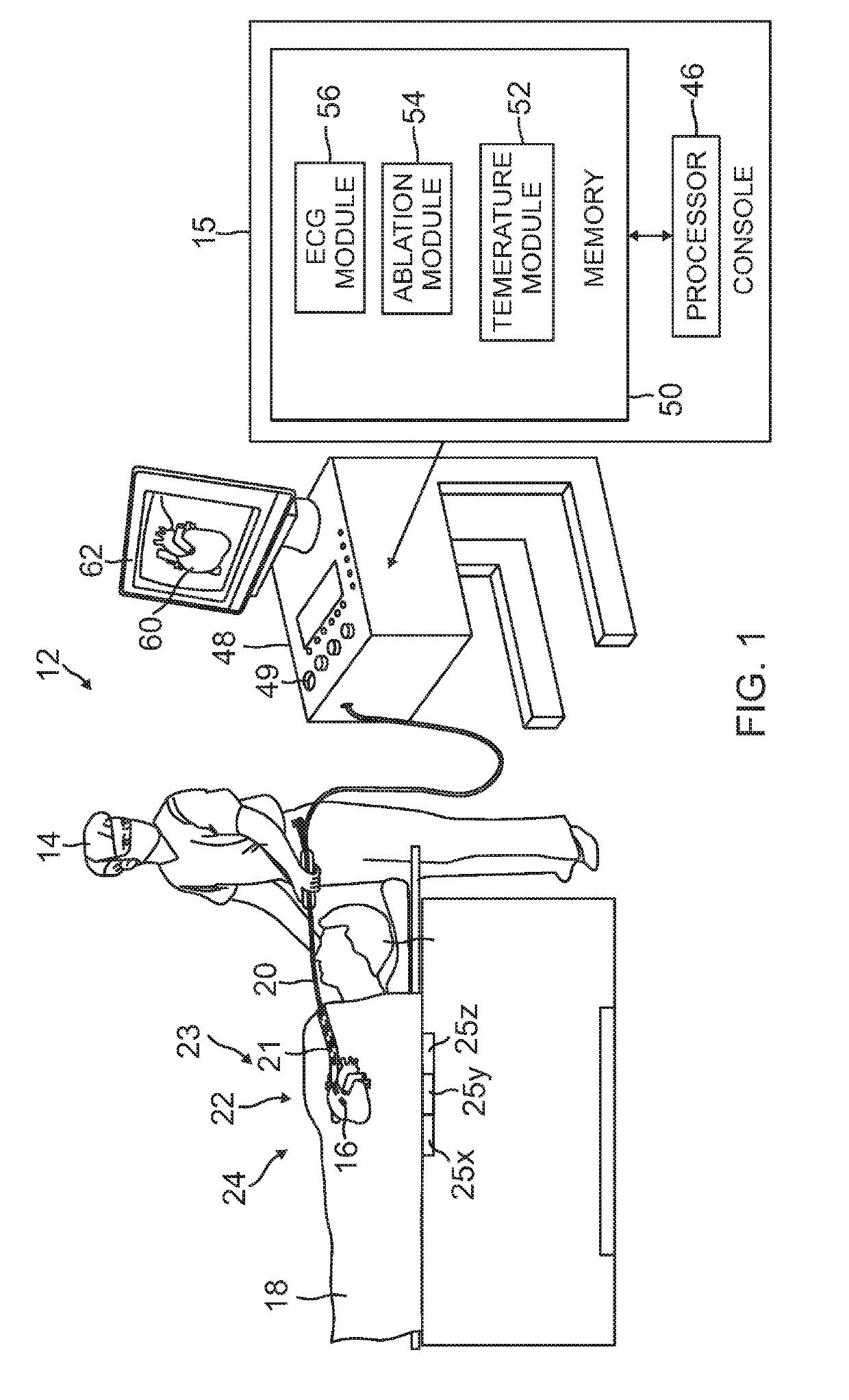
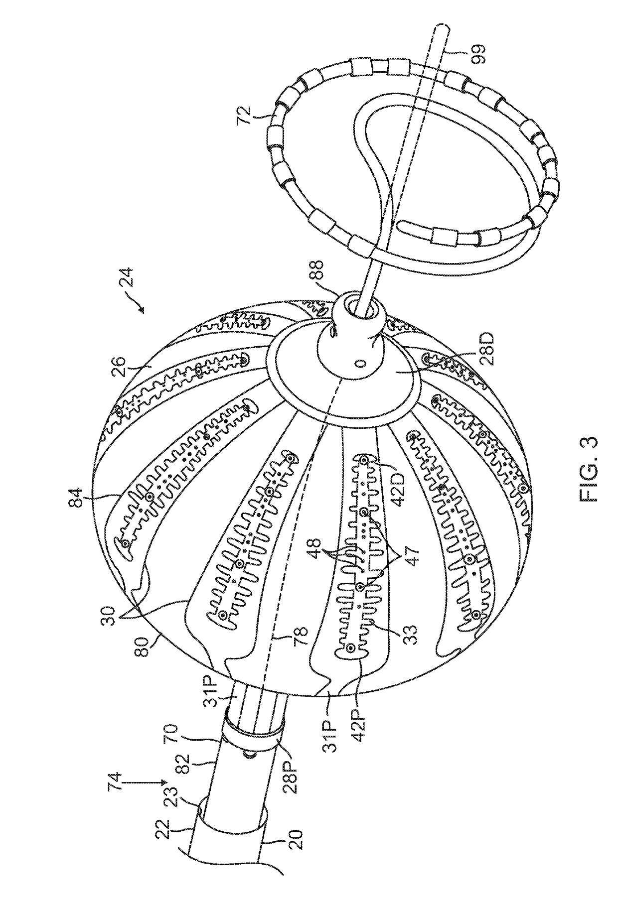
An electrophysiology catheter is disclosed having a balloon with a membrane. Electrodes may be disposed on the membrane. Each electrode may include a radiopaque marker. The markers may have different forms, e.g., alphanumeric or polygonal, to facilitate visualization of the electrodes using a bi-stable image and allow for selection of the appropriate electrodes to be energized during ablation of tissue. The inventive subject matter allows for proper orientation of electrodes on the balloon under a two-dimensional imaging system. This allows the operator or physician to determine if certain electrodes are adjacent or contiguous to the posterior surface of the left atrium and ablate such posterior surface for shorter duration or at a lower power to create an effective transmural lesion on the posterior wall of the left atrium while reducing the chances of damaging the adjacent anatomical structures.

Description

FIELD[0001]The subject matter disclosed herein relates to electrophysiologic catheters, particularly those capable of ablating cardiac tissue.BACKGROUND[0002]Ablation of cardiac tissue has been used to treat cardiac arrhythmias. Ablative energies are typically provided to cardiac tissue by a tip portion which can deliver ablative energy alongside the tissue to be ablated. Some of these catheters administer ablative energy from various electrodes three-dimensional structures. Ablative procedures incorporating such catheters may be visualized using fluoroscopy.SUMMARY OF THE DISCLOSURE[0003]While fluoroscopic visualization of cardiac devices is an established means of visualization that is simpler to use than a magnetic location and impedance system for electrophysiology procedures (EP), it is only currently used to judge overall device location relative to the cardiac silhouette. When contemplating the use of multi-electrode devices for EP with fluoroscopic imaging, the limitations o...

Claims


Application Information

Patent Timeline
IPC IPC(8): A61B18/14A61B18/12
CPCA61B6/485A61B2018/0022A61B2018/144A61B2018/00839A61B18/1206A61B2018/00363A61B2018/00375A61B2018/00791A61B2018/00982A61B18/1492A61B2090/3966A61B2018/00577A61B18/14A61B18/1482A61B2018/00351A61B2018/1407A61B2018/143A61B2218/002A61B2018/00875A61B2018/00642A61B2018/00702A61B2018/00732A61B2018/00761A61B2018/0075A61B2034/2051A61B6/487A61B6/12A61B6/503
Inventor CLARK, JEFFREY L.BANANDO, MICHAEL D.BEECKLER, CHRISTOPHER T.EGHBAL, DARIUS D.HERRERA, KEVIN J.KEYES, JOSEPH T.BIRCHARD, CHRISTOPHER
Owner BIOSENSE WEBSTER (ISRAEL) LTD
Learn More