Moving body

a moving body and body technology, applied in the field of moving bodies, can solve problems such as failure or malfunction of equipment parts, and achieve the effect of suppressing the rise in the temperature of the light source and high-luminance ligh

Inactive Publication Date: 2019-10-03
SHARP KK
View PDF0 Cites 6 Cited by
  • Summary
  • Abstract
  • Description
  • Claims
  • Application Information

AI Technical Summary

Benefits of technology

[0015]An aspect of the present invention brings about an effect of making it possible to provide a moving body, including a light source, that is capable of suppressing a rise in temperature of the light source and emitting high-luminance light from the light source.

Problems solved by technology

As sensors, electronic equipment, and the like generate heat during operation, the concentration of sensors and electronic equipment in the central part leads to a rise in temperature of the central part, undesirably causing these pieces of equipment to malfunction or fail.

Method used


Image

  • Moving body
  • Moving body
  • Moving body

Examples


embodiment 1

[0038]The following describes an unmanned aircraft 1A with reference to FIGS. 1 to 6 as a moving body according to Embodiment 1 of the present invention that gains propulsion through a fan.

[0039](Configuration of Unmanned Aircraft 1A)

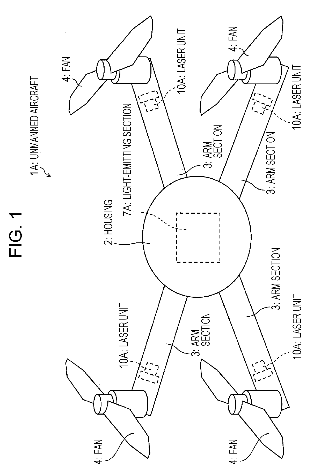
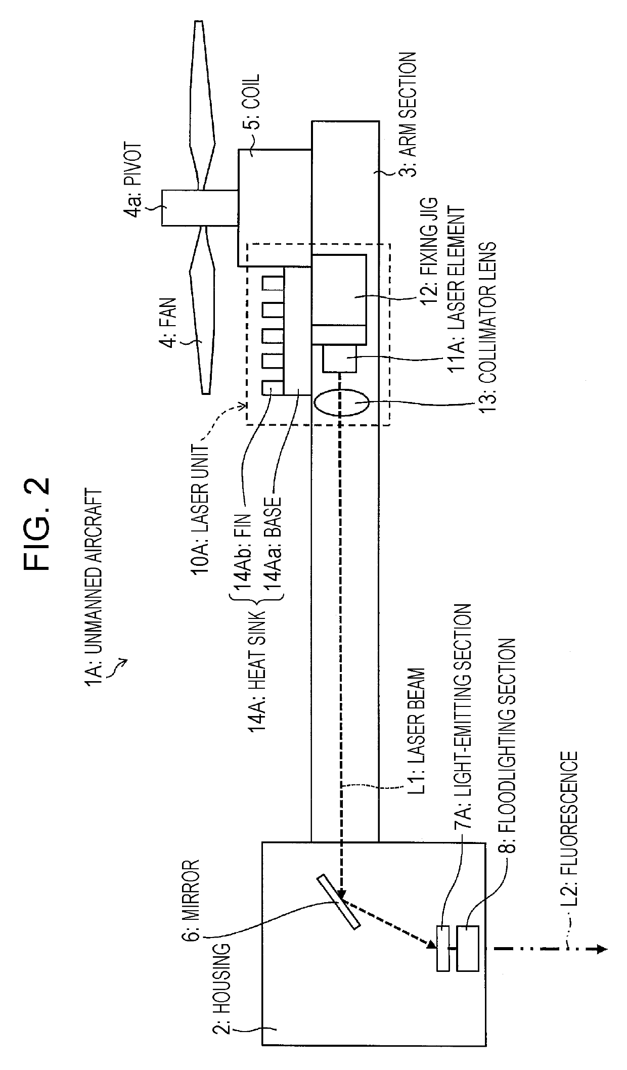
[0040]A configuration of the unmanned aircraft 1A is described with reference to FIGS. 1 and 2. FIG. 1 is a schematic view showing an overall configuration of the unmanned aircraft 1A. FIG. 2 is a cross-sectional view showing a configuration of the unmanned aircraft 1A.

[0041]As shown in FIGS. 1 and 2, the unmanned aircraft 1A includes a housing (body section) 2, arm sections 3, fans 4, coils 5, laser units (light sources) 10A, a mirror 6, a light-emitting section 7A, and a floodlighting section 8.

[0042]The housing 2 serves to house a control section (not illustrated), a sensor (not illustrated), a battery (not illustrated), and the like that are used for performing advanced flight operation of the unmanned aircraft 1A. Further, the housing 2 also houses...

embodiment 2

[0098]Another embodiment of the present invention is described below with reference to FIGS. 9 and 10. For convenience of explanation, members having the same functions as those described in the foregoing embodiment are given the same signs and, as such, are not described here.

[0099]An unmanned aircraft 1B according to the present embodiment differs from the unmanned aircraft 1A according to Embodiment 1 in terms of the position where a heat sink 14B of a laser unit 10B is provided.

[0100]A configuration of the unmanned aircraft 1B is described with reference to FIGS. 9 and 10. FIG. 9 is a cross-sectional view showing a configuration of the unmanned aircraft 1B. FIG. 10 is a top view of a fan 4 and the area therearound in the unmanned aircraft 1B in a state where the fan 4 is rotating.

[0101]As shown in FIGS. 9 and 10, a laser unit 10B of the unmanned aircraft 1B includes a heat sink 14B. The heat sink 14B includes a base 14Ba and fins 14Bb.

[0102]In the unmanned aircraft 1B, a part of...

embodiment 3

[0110]Another embodiment of the present invention is described below with reference to FIG. 12. For convenience of explanation, members having the same functions as those described in the foregoing embodiments are given the same signs and, as such, are not described here.

[0111]An unmanned aircraft 1C according to the present embodiment differs from the unmanned aircraft 1A according to Embodiment 1 in that a laser beam L1 emitted from a laser unit 10C is radiated to the light-emitting section 7A via an optical fiber 30.

[0112]A configuration of the unmanned aircraft 1C is described with reference to FIG. 12. FIG. 12 is a cross-sectional view showing a configuration of the unmanned aircraft 1C.

[0113]As shown in FIG. 12, the unmanned aircraft 1C includes a laser unit 10C, an optical fiber 30, a condensing lens 31, and a collimator lens 32.

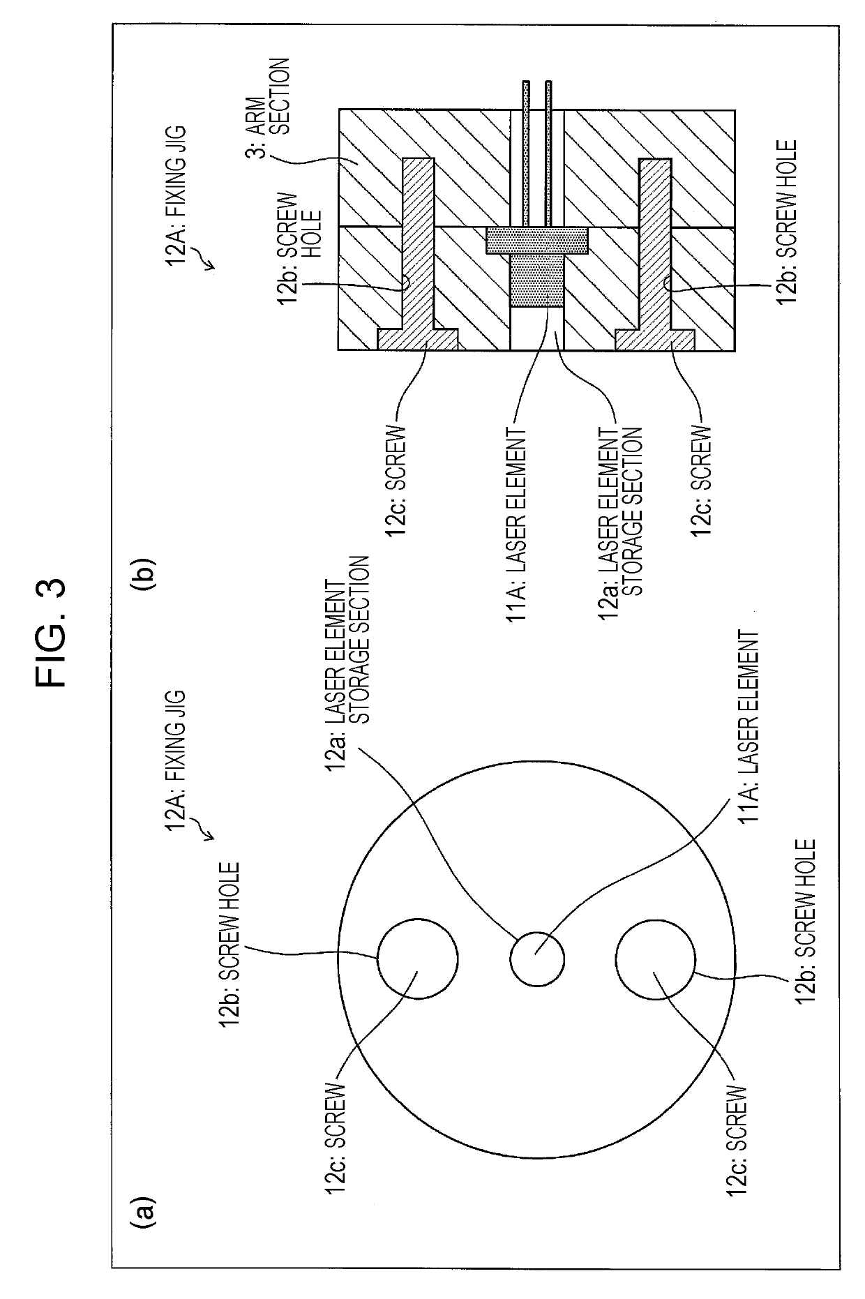
[0114]The laser unit 10C includes a laser element 11A, a fixing jig 12, and a heat sink 14A, and emits a laser beam L1.

[0115]The condensing lens 31 i...


PUM


Abstract

A moving body is provided that is capable of suppressing a rise in temperature of a light source and radiating high-luminance light. An unmanned aircraft (1A) is an unmanned aircraft that gains propulsion through a fan (4), including a laser unit (10A) that emits a laser beam (L1), wherein the laser unit (10A) has its heat dissipation efficiency enhanced by air that is blasted by the fan (4).

Description

TECHNICAL FIELD[0001]The present invention relates to a moving body including a fan that serves as a propulsion device.BACKGROUND ART[0002]The development and commercialization of unmanned aircrafts called UAV (unmanned aerial vehicles) or drones have long been on the way. Moreover, thanks to the miniaturization of sensors, the miniaturization and enhanced performance of communications and control equipment, and the like, the commercialization of unmanned aircrafts in the private sector has recently become active.[0003]Recently commercialized unmanned aircrafts are mostly of a multicopter type with a plurality of fans (propellers). Such a type of unmanned aircraft is capable of stable hovering flight, i.e. of staying in one place in the air, and has a great advantage in that its attitude can be easily controlled with respect to the place it stays in the air.[0004]An unmanned aircraft has a central part (terminal part) in which sensors and electronic equipment for performing advanced...

Claims


Application Information

Patent Timeline
Patent Type & Authority Applications(United States)
IPC IPC(8): B64C39/02B64D47/00F21V29/503F21V29/70F21V29/67F21V9/30F21V8/00
CPCB64C2201/108G02B6/0008F21V29/67B64D47/00B64C39/024B64C2201/027F21V29/70F21V9/30F21V29/503F21V33/00F21V29/76G02B6/4214G03B21/16H04N9/3129B64D47/04H04N9/3173H04N9/3141B64U10/13B64U50/19B64U30/20B64U2101/00B64C39/02F21V13/00B64C27/08F21L4/00
Inventor MORITA, TAKATOSHI
Owner SHARP KK
Why Eureka
Try Eureka