Display device

Active Publication Date: 2019-10-03
AU OPTRONICS CORP
View PDF11 Cites 1 Cited by
  • Summary
  • Abstract
  • Description
  • Claims
  • Application Information

AI Technical Summary

Benefits of technology

[0005]The disclosure provides a dis

Problems solved by technology

As compared with display panel in VA mode, the display panel in IPS mode and/or FFS mode has better display quality (i.e., with wider viewing angle) at a large viewing angle, but the performance related to dark-state and contrast of the display panel in IPS mode and/or F

Method used


Image

  • Display device
  • Display device
  • Display device

Examples


first embodiment

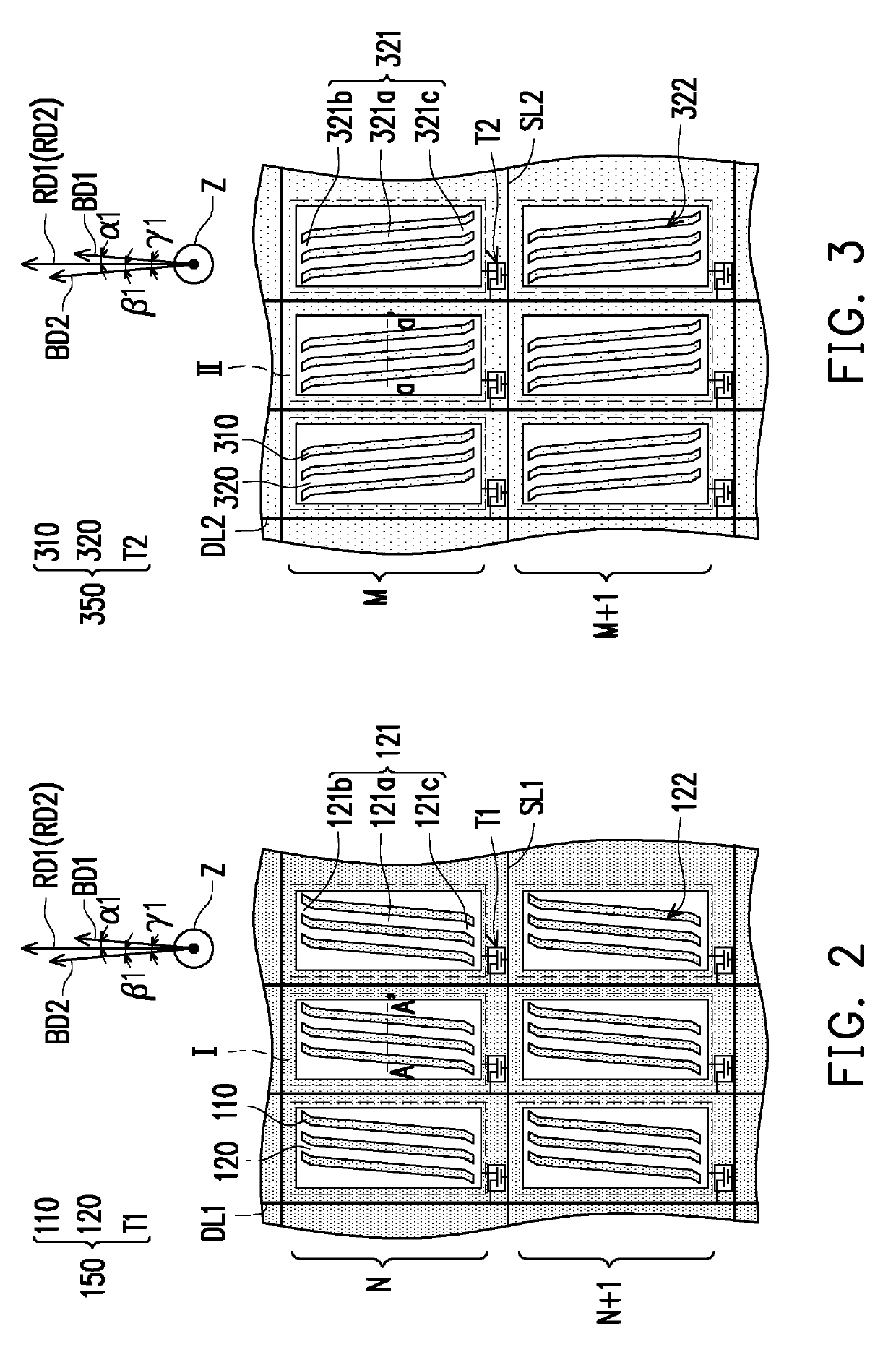
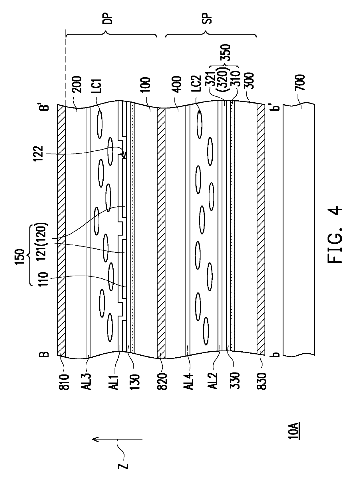
[0075]Referring to FIG. 4, FIG. 5 and FIG. 6, first liquid crystal molecules LC1 and second liquid crystal molecules LC2 of the display device 10A in the embodiment are positive-type liquid crystal molecules. The difference between the display device 10A in the embodiment and the display device 10 in the first embodiment is that the first rubbing direction RD1 of the first alignment film AL1 of the display device 10A in the embodiment is substantially perpendicular to the second rubbing direction RD2 of the second alignment film AL2, and the first extending direction BD1 of each of the pixel structures 150 is substantially perpendicular to the second extending direction BD2 of each of the light valves 350.

[0076]Referring to FIG. 5 and FIG. 6, in the embodiment, an included angle α2 is formed between the first rubbing direction RD1 and the first extending direction BD1, and an included angle β2 is formed between the second rubbing direction RD2 and the second extending direction BD2....

second embodiment

[0086]Referring to FIG. 16, FIG. 17 and FIG. 18, the difference between the display device 10E in the embodiment and the display device 10A in the second embodiment is that the second extending direction BD2 of the light valve 350 of the display device 10E in the embodiment is parallel with the first extending direction BD1 of the pixel structure 150, the plurality of first liquid crystal molecules LC1 are positive-type liquid crystal molecules, and the plurality of second liquid crystal molecules LC2 are negative-type liquid crystal molecules.

[0087]Referring to FIG. 17 and FIG. 18, in the embodiment, an included angle α4 is formed between the first rubbing direction RD1 and the first extending direction BD1, and an included angle β4 is formed between the second rubbing direction RD2 and the second extending direction BD2. Specifically, in the embodiment, the included angle β4 is larger than the included angle α4, and the included angle β4 satisfies the equation below: β4=90°+α4, wh...

sixth embodiment

[0089]Referring to FIG. 19, FIG. 20 and FIG. 21, the difference between the display device 10F in the embodiment and the display device 10E in the sixth embodiment is that the plurality of first liquid crystal molecules LC1 of the display device 10F in the embodiment are negative-type liquid crystal molecules, and the plurality of second liquid crystal molecules LC2 are positive-type liquid crystal molecules, which should not be construed as a limitation to the disclosure.

[0090]Referring to FIG. 20 and FIG. 21, in the embodiment, an included angle α4 between the first rubbing direction RD1 and the first extending direction BD1 is larger than an included angle β4 between the second rubbing direction RD2 and the second extending direction BD2. Specifically, in the embodiment, the included angle α4 satisfies the equation below: α4=90°+β4. In the embodiment, the display device 10F has effects and advantages similar to that of the display device 10 in the first embodiment, and thus no re...


PUM

PropertyMeasurementUnit
Fractionaaaaaaaaaa
Angleaaaaaaaaaa
Angleaaaaaaaaaa

Abstract

A display device includes a first substrate, a second substrate, a plurality of first liquid crystal molecules, a plurality of pixel structures, a third substrate, a fourth substrate, a plurality of second liquid crystal molecules, a plurality of light valves and a backlight source. Each of the plurality of pixel structures includes a pixel electrode and a common electrode. At least one of the pixel electrode and the common electrode includes a plurality of first branches extended along a first extending direction. Each of the plurality of light valves includes a first electrode and a second electrode. At least one of the first electrode and the second electrode includes a plurality of second branches extended along a second extending direction. The plurality of first branches and the plurality of second branches are overlapped. The plurality of light valves are disposed between the backlight source and the plurality of pixel structures.

Description

CROSS-REFERENCE TO RELATED APPLICATION[0001]This application claims the priority benefit of Taiwan application serial no. 107111600, filed on Apr. 2, 2018. The entirety of the above-mentioned patent application is hereby incorporated by reference herein and made a part of this specification.BACKGROUNDField of the Disclosure[0002]The disclosure is related to an electronic device, and particularly to a display device.Description of Related Art[0003]Liquid crystal display has the advantage of being compact with low power consumption and thus has replaced conventional cathode ray tube in the multi-media display field for the past twenty years, and even stands out as being developed beyond the level of many known display techniques in the market such as plasma display, field emission display and so on. Among known liquid crystal display techniques, liquid crystal driving technique may be classified into two types: one is vertical electrical field driving mode coordinated with negative-ty...

Claims


Application Information

Patent Timeline
IPC IPC(8): G02F1/1337G02F1/1343
CPCG02F1/134309G02F1/133784G02F2001/134381G02F2201/123G02F2001/134345G02F2203/01G02F1/133723G02F2001/134318G02F1/133711G02F1/134363G02F1/13471G02F1/134372G02F1/134318G02F1/134345G02F1/134381
Inventor CHEN, JU-CHINLEE, SEOK-LYUL
Owner AU OPTRONICS CORP
Why Eureka
Try Eureka