

X-ray tube
- Summary
- Abstract
- Description
- Claims
- Application Information
AI Technical Summary
Benefits of technology
Problems solved by technology
Method used
Image

Examples
first embodiment
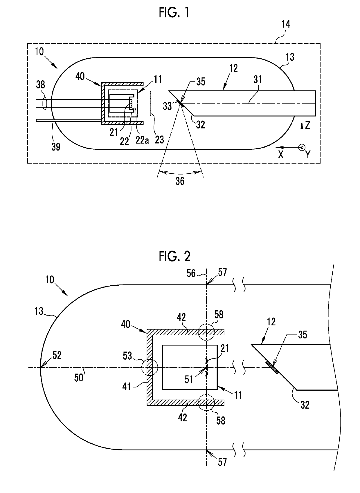
[0079]As illustrated in FIG. 1, an X-ray tube 10 comprises a cathode assembly 11 including a cathode, an anode 12, and an envelope 13. The X-ray tube 10 and a housing 14 form an X-ray tube device.
[0080]The cathode assembly 11 emits electrons. In this embodiment, the cathode assembly 11 emits electrons in a negative X direction. In this embodiment, a direction parallel to a central axis 31 of the anode 12 is referred to as the X direction, a direction that is perpendicular to the central axis 31 of the anode 12 and is in the plane of paper in the drawings is referred to as the Z direction, and a direction perpendicular to the X direction and the Z direction is referred to as the Y direction. In addition, a direction toward the left side of the plane of paper in the drawings is referred to as a positive X direction, a direction toward the upper side of the plane of paper in the drawings is referred to as a positive Z direction, and a front direction of the plane of paper in the drawin...
second embodiment
[0124]In the first embodiment and the modification examples, the first electrode 22 and the second electrode 23 are not electrically connected to the first shielding portion 41 and the second shielding portion 42. However, the first shielding portion 41 or the second shielding portion 42 can be electrically connected to the first electrode 22 or the second electrode 23. That is, the X-ray tube 10 may comprise an electrode that is electrically connected to the first shielding portion 41 or the second shielding portion 42. For example, as illustrated in FIG. 23, the second shielding portion 42 is electrically connected to the second electrode 23. In this case, the second electrode 23 is an electrode that is electrically connected to the second shielding portion 42. In addition, in FIG. 23, the first shielding portion 41 and the second shielding portion 42 are bonded and electrically connected to each other. Therefore, the second electrode 23 electrically connected to the second shield...
third embodiment
[0128]In the first and second embodiments and the modification examples, the first shielding portion 41 and the second shielding portion 42 are not bonded to the cathode assembly 11. However, a portion or the whole of the first shielding portion 41 and / or the second shielding portion 42 may be bonded to the cathode assembly 11. In this embodiment, adhesion means that components come into contact with each other and the positional relationship between the components is substantially fixed by welding, fitting, or other methods, in addition to bonding using an adhesive. For example, as illustrated in FIG. 25, the first shielding portion 41 and the cathode assembly 11 can be bonded to each other. In addition, as illustrated in FIG. 26, the second shielding portion 42 and the cathode assembly 11 can be bonded to each other. Further, as illustrated in FIG. 27, the first shielding portion 41 and the second shielding portion 42 can be bonded to the cathode assembly 11. In a case in which th...
PUM
 Abstract
Description
Claims
Application Information