A Hearing Device,A Hearing Device System and A Method Performed in A Hearing Device

a hearing device and hearing technology, applied in the direction of behind the ear hearing aids, hearing aid housings, hearing aids, etc., can solve the problems that the use of leds as optical receivers may not provide high bandwidth, and engineers might not consider such a solution, so as to improve the efficiency of the hearing device and reduce the cost of the hearing device. , the effect of allowing the safe space of the hearing devi

Inactive Publication Date: 2019-10-03
SONOVA AG
View PDF5 Cites 1 Cited by
  • Summary
  • Abstract
  • Description
  • Claims
  • Application Information

AI Technical Summary

Benefits of technology

[0010]The inventive hearing device advantageously exploits the light emitting diode LED to operate as an output device as well as an input device. Therefore, advantageously, the present invention allows reusing of existing components comprised by the hearing device, i.e. reusing of the light emitting diode, with minimum additional elements, in order to provide a bidirectional optical communication link for digital data transfer from an external device, i.e. a charging device, a remote control or a fitting station, to the hearing device which may comprise a memory. While light emitting diodes are known to be light emitters, it has been observed that they can also be used as light receivers. In other words, signalling is also possible by using the light emitting diode as a receiver. Using an LED as an optical receiver may not provide high bandwidth as with dedicated optical receivers. Therefore an engineer might not consider such a solution. This feature encompasses an arrangement for signal conditioning as well as an input circuit. The inventive reuse or rather dual function of the at least one light emitting diode results in cost savings of the hearing device as a whole. Further, advantageously, the omission of a further (receiving) component allows to safe space of the hearing device.

Problems solved by technology

Using an LED as an optical receiver may not provide high bandwidth as with dedicated optical receivers.
Therefore an engineer might not consider such a solution.

Method used


Image

  • A Hearing Device,A Hearing Device System and A Method Performed in A Hearing Device
  • A Hearing Device,A Hearing Device System and A Method Performed in A Hearing Device
  • A Hearing Device,A Hearing Device System and A Method Performed in A Hearing Device

Examples


Embodiment Construction

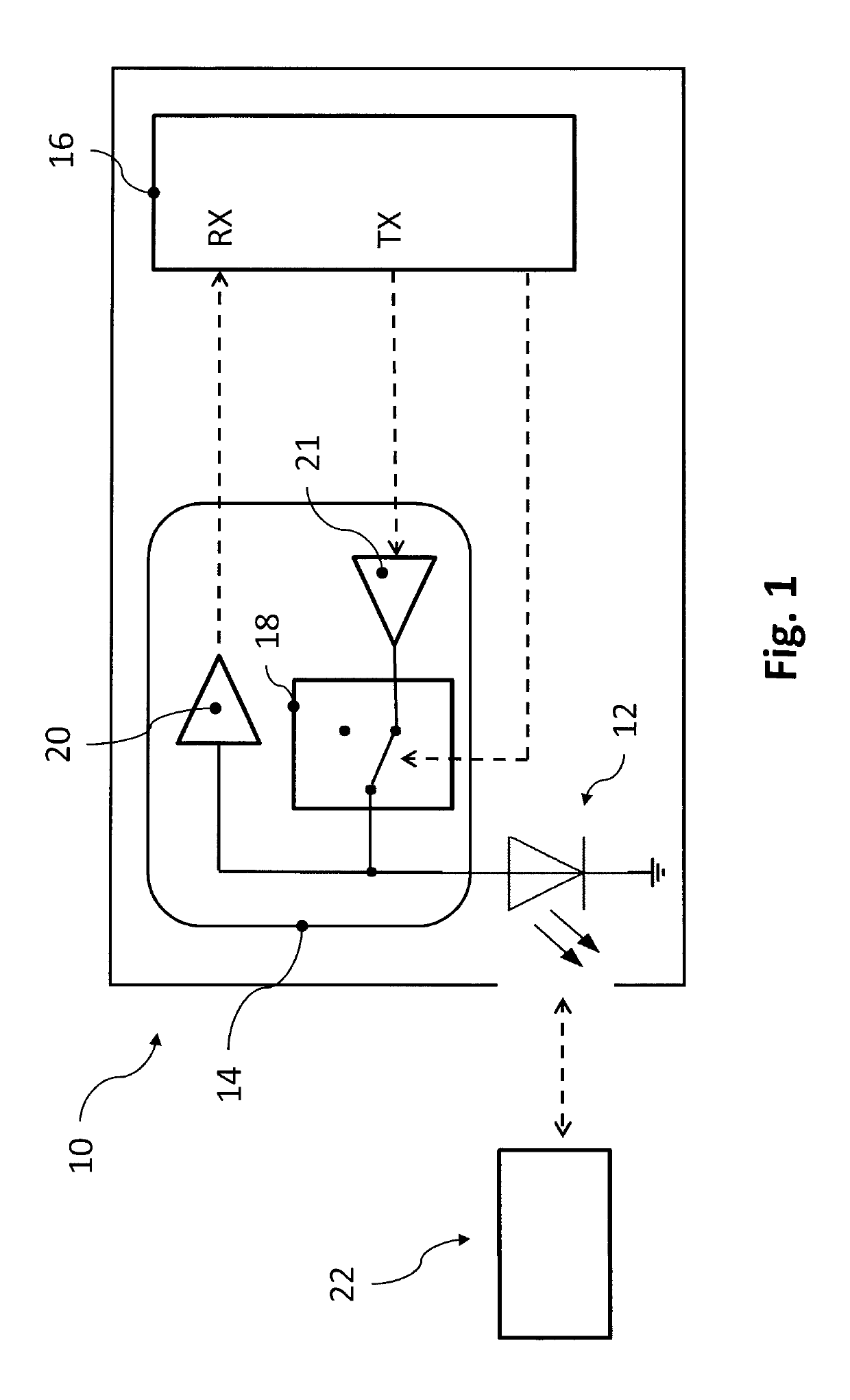
[0034]FIG. 1 schematically depicts a hearing device 10 according to an embodiment of the invention. The hearing device 10 comprises a light emitting diode (LED) 12, a control unit 14 and a processor 16. The processor 16 may comprise or be connected to a memory (not separately shown). The control unit 14 comprises a switch 18 which may connect the LED 12 to a data output TX of the processor 16. Optionally the control unit 14 may comprise an LED-driver (not separately shown). Once the switch 18 connects the LED 12 to the data output TX of the processor 16 the hearing device 10 is in transmission mode. Once the switch 18 disconnects the LED 12 from the data output TX of the processor 16 the hearing device 10 is in receiving mode.

[0035]The hearing device 10 comprises a buffer 20 coupled to the LED 12. Said buffer 20 is adapted to convert a voltage of the LED 12 into a digital code, in particular a binary code, and thereby provides a data stream RX data which is fed to a data input RX of...


PUM


Abstract

The present invention relates to a hearing device (10) comprising a processor (16) and a control unit (14) connected to each other. The hearing device (10) further comprises at least one light emitting diode (12) operatively connected to the control unit (14), wherein said control unit (14) is adapted to switch the operational mode of the at least one light emitting diode (12) such to operate in a transmittal mode or a reception mode.

Description

TECHNICAL FIELD[0001]The present invention is related to a hearing device, a hearing device system and a method performed in a hearing device.BACKGROUND OF THE INVENTION[0002]Hearing devices are typically used to improve the hearing capability or communication capability of a user. A hearing device may pick up the surrounding sound with a microphone of the hearing device, process the microphone signal thereby taking into account the hearing preferences of the user of the hearing device and provide the processed sound signal into an ear canal of the user via a miniature loudspeaker, commonly referred to as a receiver. A hearing device may also receive sound from an alternative input such as an induction coil or a wireless interface. A hearing device may comprise a light emitting diode for signalling status information to the user.[0003]Hearing aides are hearing devices, which are worn at the ear of a user. The sound processing is optimized in order to compensate for hearing impairmen...

Claims


Application Information

Patent Timeline
Patent Type & Authority Applications(United States)
IPC IPC(8): H04R25/00
CPCH04R25/65H04R2225/33H04R25/554H04R25/558H04R2225/021H04R2225/025H04R2225/31
Inventor AAZAMI, SAHBALAUBER, JOEL
Owner SONOVA AG
Why Eureka
Try Eureka