
Methods and systems for changing a refractive property of an implantable intraocular lens

a technology of refractive properties and implants, which is applied in the field of methods and systems for changing the refractive properties of implantable intraocular lenses, can solve the problems of reducing the perception of blue colors, vision loss, and potentially blinding

Active Publication Date: 2019-10-10
AMO DEVMENT
View PDF0 Cites 14 Cited by
  • Summary
  • Abstract
  • Description
  • Claims
  • Application Information

AI Technical Summary

Benefits of technology

The patent describes a method for altering the refractive property of a crosslinked acrylic polymer used in an implantable intraocular lens. The method involves using a laser to irradiate the lens with a light beam, resulting in a change in refractive index that affects its refractive property. The change in refractive index is controlled by the total energy of the laser beam and can be linearly related to the pre-irradiation refractive index. The method can produce a negative change in refractive index during the first few seconds after irradiation, followed by a positive change a few nanoseconds later. The refractive index change is stable over a long period of time. The invention also provides a method for compensating for multi-photon absorption and thermal lensing effects. The technical effect of the invention is to improve the precision and accuracy of refractive index modification in the crosslinked acrylic polymer used in implantable intraocular lenses.

Problems solved by technology

Early in the development of age-related cataract the power of the lens may be increased, causing near-sightedness (myopia), and the gradual yellowing and opacification of the lens may reduce the perception of blue colors as those wavelengths are absorbed and scattered within the crystalline lens.
Cataract typically progresses slowly to cause vision loss and are potentially blinding if untreated.
However, post-surgical visual acuity in patients with a newly implanted IOL is often imperfect.

Method used


Image

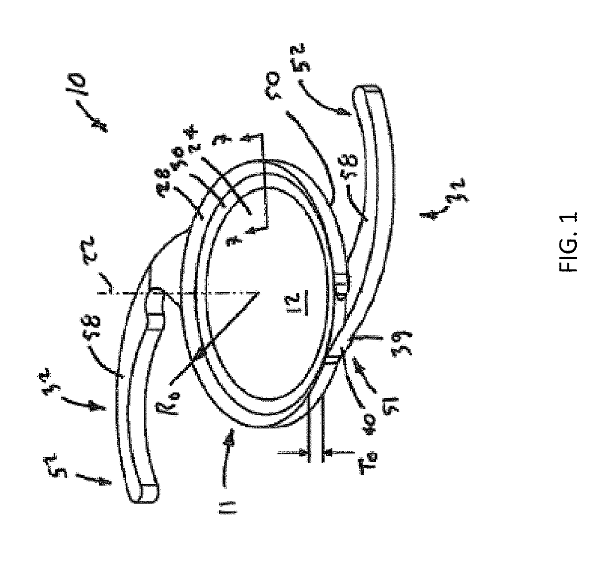
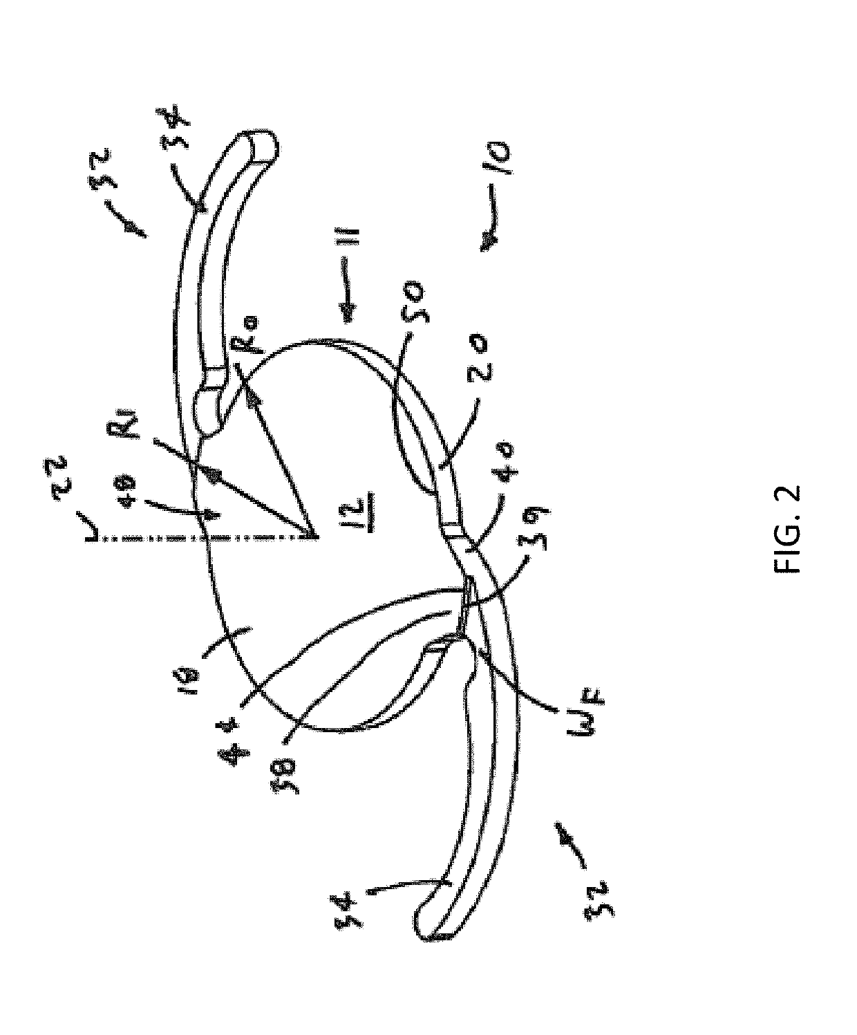
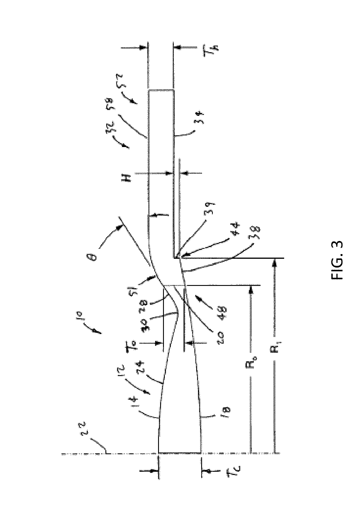
  • Methods and systems for changing a refractive property of an implantable intraocular lens
  • Methods and systems for changing a refractive property of an implantable intraocular lens
  • Methods and systems for changing a refractive property of an implantable intraocular lens

Examples


Embodiment Construction

[0041]In many embodiments, a method of altering a refractive property of a crosslinked acrylic polymer comprises generating a light beam with a light source; and irradiating the crosslinked acrylic polymer with the light beam, thereby producing a predetermined change in a refractive property of the crosslinked acrylic polymer. Preferably, irradiation with the laser light beam results in a change in refractive index of the cross-linked acrylic polymer, thereby causing the predetermined change in the refractive property. In some embodiments, a first change in the refractive index is negative during a first time period after irradiation and a second change in the refractive index is positive in a second time period after irradiation. In some embodiments, a change in refractive index of the cross-linked acrylic polymer relative to the pre-irradiation refractive index at a location within the crosslinked acrylic polymer is linearly related with a total energy of the irradiation with the ...


PUM

PropertyMeasurementUnit
Lengthaaaaaaaaaa
Timeaaaaaaaaaa
Timeaaaaaaaaaa

Abstract

A method of altering a refractive property of a crosslinked acrylic polymer material by irradiating the material with a high energy pulsed laser beam to change its refractive index. The method is used to alter the refractive property, and hence the optical power, of an implantable intraocular lens after implantation in the patient's eye. In some examples, the wavelength of the laser beam is in the far red and near IR range and the light is absorbed by the crosslinked acrylic polymer via two-photon absorption at high laser pulse energy. The method also includes designing laser beam scan patterns that compensate for effects of multiphone absorption such as a shift in the depth of the laser pulse absorption location, and compensate for effects caused by high laser pulse energy such as thermal lensing. The method can be used to form a Fresnel lens in the optical zone.

Description

CROSS REFERENCE TO RELATED APPLICATIONS[0001]This application claims the benefit under 35 U.S.C. § 119(e) of U.S. Provisional Patent Application Nos. 62 / 654,192, filed Apr. 6, 2018 and 62 / 720,882, filed Aug. 21, 2018, which are incorporated herein by reference in their entirety.BACKGROUND OF THE INVENTION[0002]Cataract extraction is one of the most commonly performed surgical procedures in the world. A cataract is the opacification of the crystalline lens or its envelope—the lens capsule—of the eye. It varies in degree from slight to complete opacity that obstructs the passage of light. Early in the development of age-related cataract the power of the lens may be increased, causing near-sightedness (myopia), and the gradual yellowing and opacification of the lens may reduce the perception of blue colors as those wavelengths are absorbed and scattered within the crystalline lens. Cataract typically progresses slowly to cause vision loss and are potentially blinding if untreated.[0003...

Claims


Application Information

Patent Timeline
IPC IPC(8): A61F2/16B29D11/02
CPCA61F2250/0053A61F2002/1681A61F2009/00851A61F2/1635A61F2/1648A61F2/1602A61F2/164B29D11/023A61F2/1627A61L2430/16G02C7/022A61F9/008A61F2009/00842A61F2009/0087B29C71/04B29C2035/0838B29C2791/009B29D11/00461B29K2995/0031G02C2202/12A61F2/16
Inventor SCHUELE, GEORGVANKOV, ALEXANDERWANG, JENNYDEWEY, DAVID A.WANG, TIANHENGWILTBERGER, MICHAELSTATE, MIHAIGOODING, PHILLIP
Owner AMO DEVMENT
Learn More