Ceramic tile leveling bracket, pushing and clamping pliers and ceramic tile leveling and laying system

a technology for leveling brackets and ceramic tiles, which is applied in the direction of pliers, covering/linings, constructions, etc., can solve the problems of low construction efficiency and high requirements for construction personnel, and achieve the effects of facilitating large-scale application, simple and convenient operation, and effective improvement of laying efficiency and leveling quality

Active Publication Date: 2019-10-10
HANGZHOU GREAT STAR IND CO LTD
View PDF5 Cites 8 Cited by
  • Summary
  • Abstract
  • Description
  • Claims
  • Application Information

AI Technical Summary

Benefits of technology

[0006]An object of the present invention is to provide a ceramic tile leveling and laying device, which solves the problems of the prior art, such as complicated leveling and laying processes, low laying efficiency, and high technical requirements for operators.
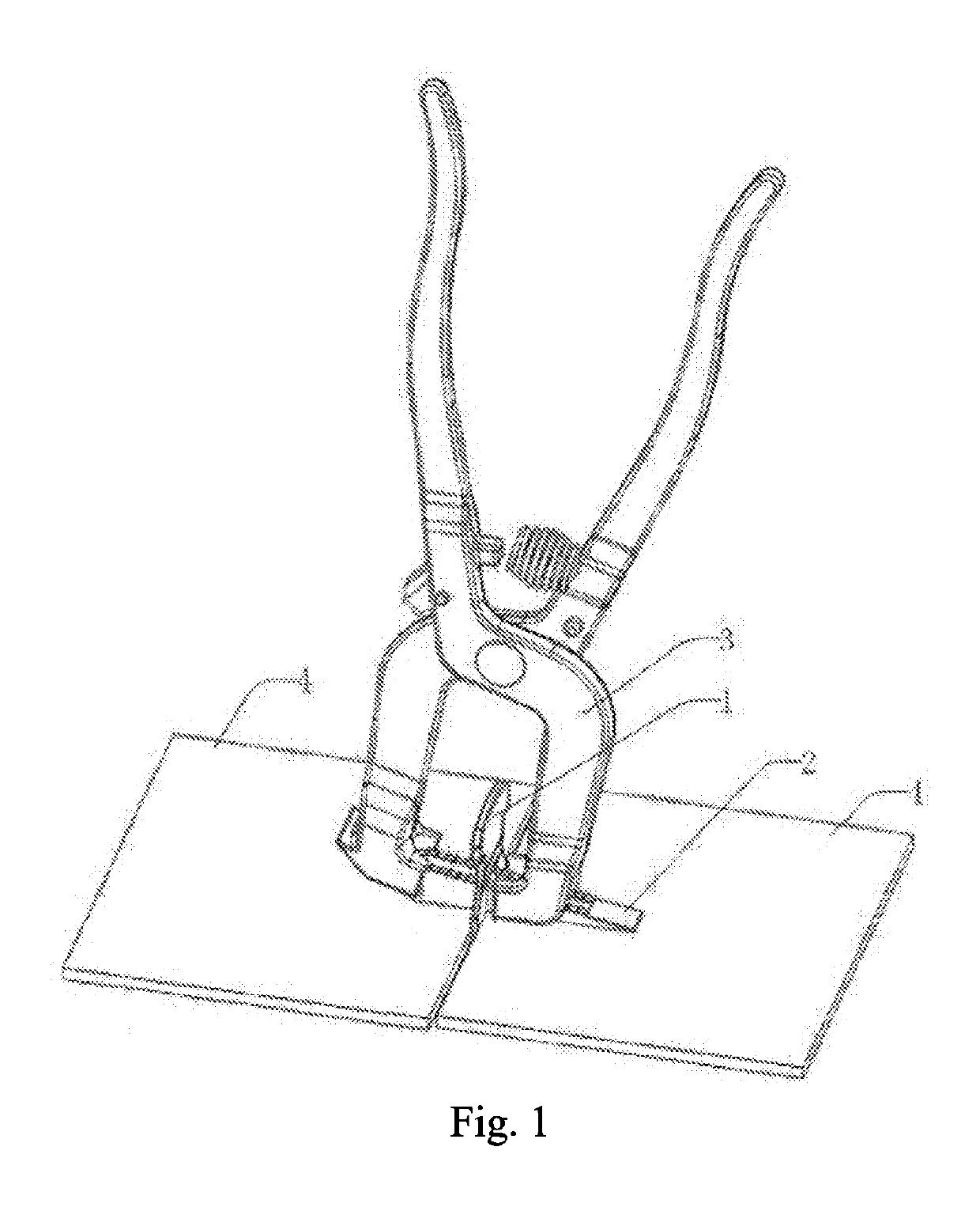
[0027]The present invention has the advantages that, by providing a ceramic tile leveling bracket, pushing and clamping pliers and a ceramic tile leveling and laying system, in the ceramic tile laying process, the ceramic tile leveling bracket and the insertion block are used to support the junction between two adjacent ceramic tiles, so that the upper surfaces of multiple ceramic tiles in the same area are kept on the same plane, the operation is simple and convenient, and the laying efficiency and the leveling quality are effectively improved, thereby facilitating large-scale application.

Problems solved by technology

The shortcomings lie in that the flatness and fullness of the paved ceramic tile are relatively poor, and the viscosity thereof is also poor, so that it can only be applied to the pasting of small ceramic tiles, and has a large limitation; and, the workload in the pasting process is relatively large, the technical requirements for the construction personnel are high, and the construction efficiency is low.

Method used


Image

  • Ceramic tile leveling bracket, pushing and clamping pliers and ceramic tile leveling and laying system
  • Ceramic tile leveling bracket, pushing and clamping pliers and ceramic tile leveling and laying system
  • Ceramic tile leveling bracket, pushing and clamping pliers and ceramic tile leveling and laying system

Examples


Embodiment Construction

[0049]The preferred embodiments of the present invention are described below with reference to the accompanying drawings, and the present invention can be fully introduced to those skilled in the art, such that the technical content thereof will be clearer and is easy to understand. The present invention can be embodied in various forms of embodiments, and the scope of protection of the present invention is not limited to the embodiments mentioned herein.

[0050]In the drawings, the same reference numeral indicates components having the same structure, and similar reference numerals indicate assemblies having similar structures or functions throughout. The size and thickness of each assembly shown in the figures are shown arbitrarily, and the present invention does not define the size and thickness of each assembly. In order to make the illustration clearer, the thickness of the component in some places of the figures is appropriately exaggerated.

[0051]Orientation terms mentioned in t...


PUM

PropertyMeasurementUnit
angleaaaaaaaaaa
thicknessaaaaaaaaaa
heightaaaaaaaaaa

Abstract

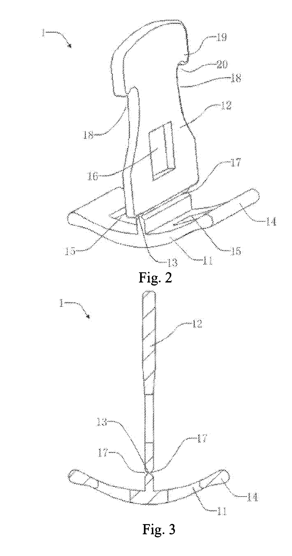
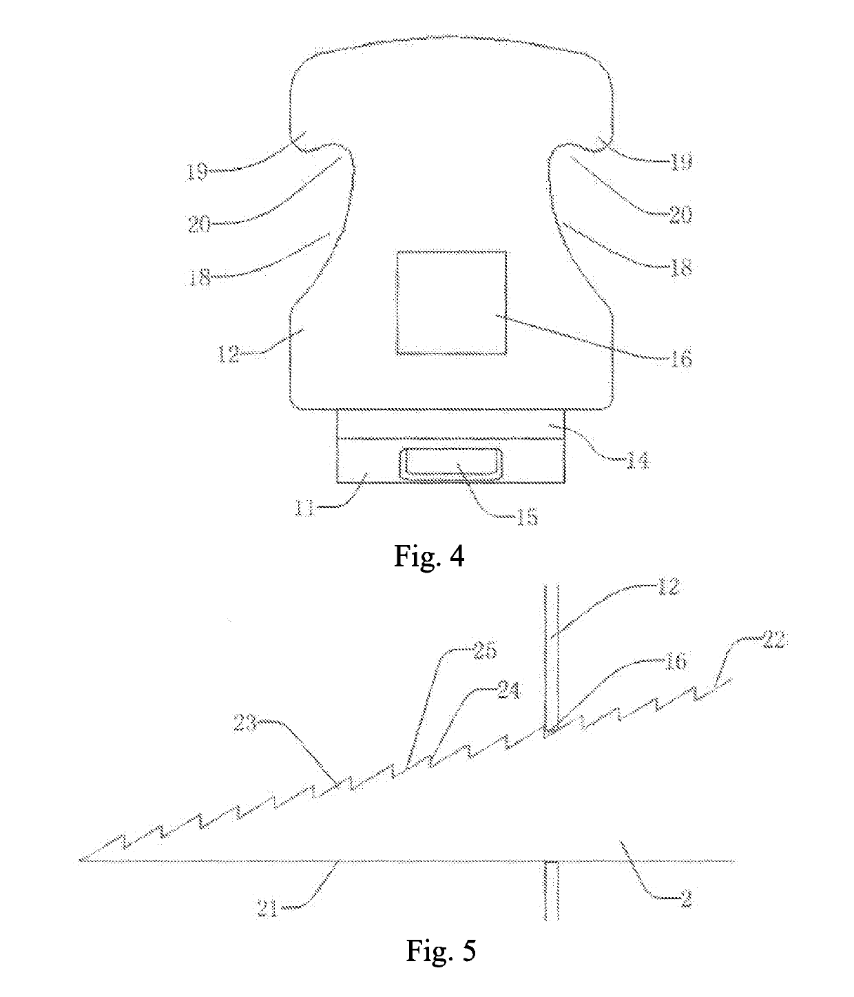
Disclosed are a ceramic tile leveling bracket, pushing and clamping pliers and a ceramic tile leveling and laying system. The ceramic tile leveling and laying system comprises: a ceramic tile leveling bracket (1), an insertion block (2) and pushing and clamping pliers (3), wherein the ceramic tile leveling bracket (1) is provided at the junction between two adjacent ceramic tiles (4), one end of the insertion block (2) is inserted into an insertion block through hole (16) of the ceramic tile leveling bracket (1), and the pushing and clamping pliers (3) push and clamp the insertion block (2) into the insertion block through hole (16), so that an insertion block bottom surface (21) is tangent to upper surfaces of the two ceramic tiles (4). The ceramic tile leveling and laying system is easy to operate, and helps to improve the laying efficiency and laying quality.

Description

TECHNICAL FIELD[0001]The present invention relates to a ceramic tile laying tool, in particular to a ceramic tile leveling bracket, pushing and clamping pliers and a ceramic tile leveling and laying system.BACKGROUND ART[0002]Ceramic tile inlaying processes often used in the building decoration industry mainly use the traditional manual paving method. The common method for paving floor ceramic tiles is generally divided into a dry laying method and a wet laying method.[0003]The wet laying method uses cement mortar or the like as an adhesive to directly paste the ceramic tile to a wall or a floor. The shortcomings lie in that the flatness and fullness of the paved ceramic tile are relatively poor, and the viscosity thereof is also poor, so that it can only be applied to the pasting of small ceramic tiles, and has a large limitation; and, the workload in the pasting process is relatively large, the technical requirements for the construction personnel are high, and the construction ef...

Claims


Application Information

Patent Timeline
Patent Type & Authority Applications(United States)
IPC IPC(8): E04F21/18E04F21/22B25B7/22
CPCE04F21/22E04F21/1877B25B7/22E04F21/0092E04F13/0892E04F15/02022B25B7/14B25B7/02B25B7/08B25B27/02
Inventor LI, YUEMING
Owner HANGZHOU GREAT STAR IND CO LTD
Why Eureka
Try Eureka