Eureka AIR delivers breakthrough ideas for toughest innovation challenges, trusted by R&D personnel around the world.

Analog-to-digital converter

Active Publication Date: 2019-10-10
MELEXIS TECH NV
View PDF0 Cites 1 Cited by
  • Summary
  • Abstract
  • Description
  • Claims
  • Application Information

AI Technical Summary

Benefits of technology

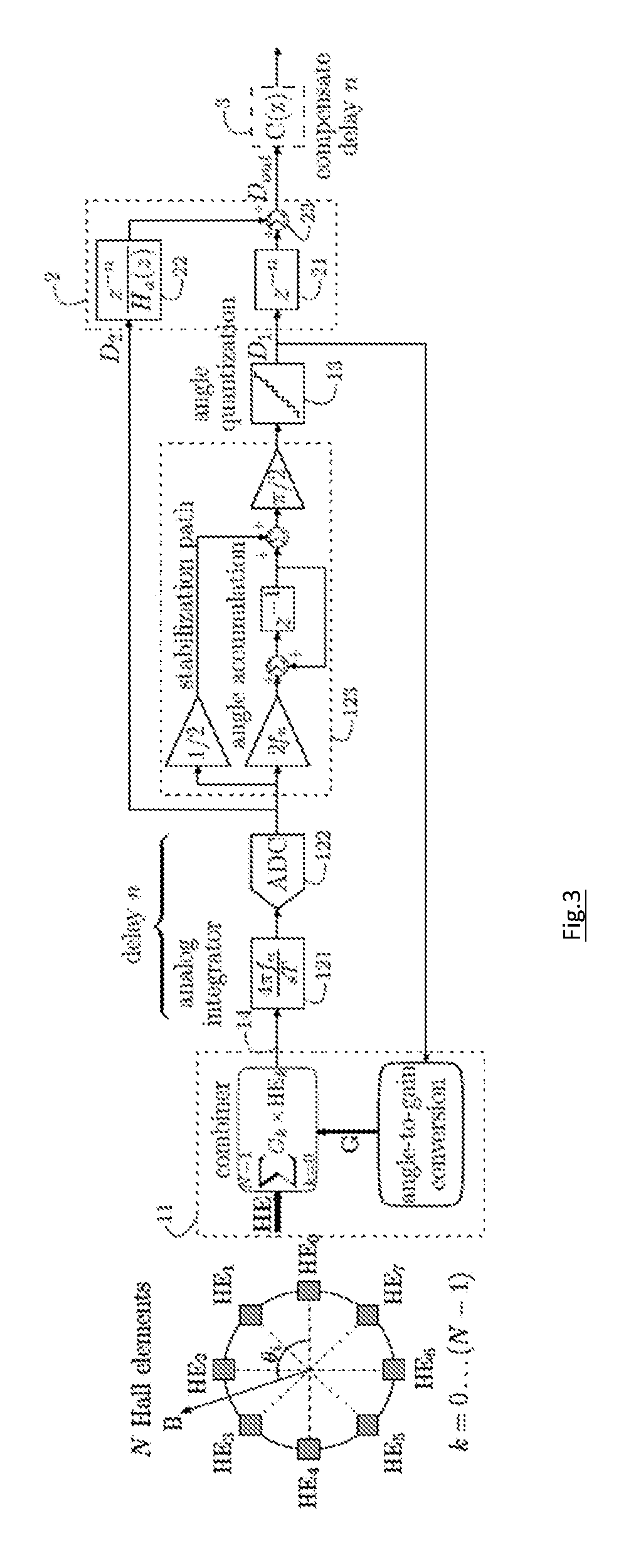
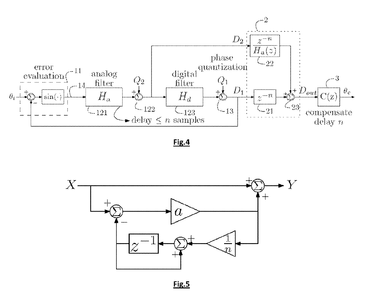
The patent describes an analog-to-digital converter that reduces quantization noise caused by the first quantizer. This is achieved by using an analog loop filter with a transfer function that matches the ratio of the first and second recombination filters. Even if there is a small deviation in the filter's transfer function, the relative deviation is still important and can still significantly reduce the quantization noise. The first and second recombination filters can also be adaptive to remove the dependency of the analog-to-digital converted output signal from the quantization noise. The analog-to-digital converter also includes a compensation filter to account for delay introduced by the first recombination filter and a digital loop filter with an accumulator / integrator and a feedforward path for improving the dynamic response of the feedback loop.

Problems solved by technology

Also, an important problem in SDMs relates to imperfections of this feedback DAC, e.g. its non-linearity.
Techniques to deal with this problem exist, e.g. dynamic elements matching or calibration approaches, but these become quite involved (e.g. in terms of required on-chip area) when the feedback DAC has many bits.
In prior art structures with dual in-loop quantization, a known technique for making the signal transfer function unity cannot be easily applied.
So, the signal transfer function of the loop cannot be easily manipulated by structural changes of the feedback loop itself, such as adding extra feed-in paths using the input signal.

Method used


Image

  • Analog-to-digital converter
  • Analog-to-digital converter
  • Analog-to-digital converter

Examples


Embodiment Construction

[0041]The present invention will be described with respect to particular embodiments and with reference to certain drawings but the invention is not limited thereto but only by the claims.

[0042]Furthermore, the terms first, second and the like in the description and in the claims, are used for distinguishing between similar elements and not necessarily for describing a sequence, either temporally, spatially, in ranking or in any other manner. It is to be understood that the terms so used are interchangeable under appropriate circumstances and that the embodiments of the invention described herein are capable of operation in other sequences than described or illustrated herein.

[0043]It is to be noticed that the term “comprising”, used in the claims, should not be interpreted as being restricted to the means listed thereafter; it does not exclude other elements or steps. It is thus to be interpreted as specifying the presence of the stated features, integers, steps or components as re...


PUM


Abstract

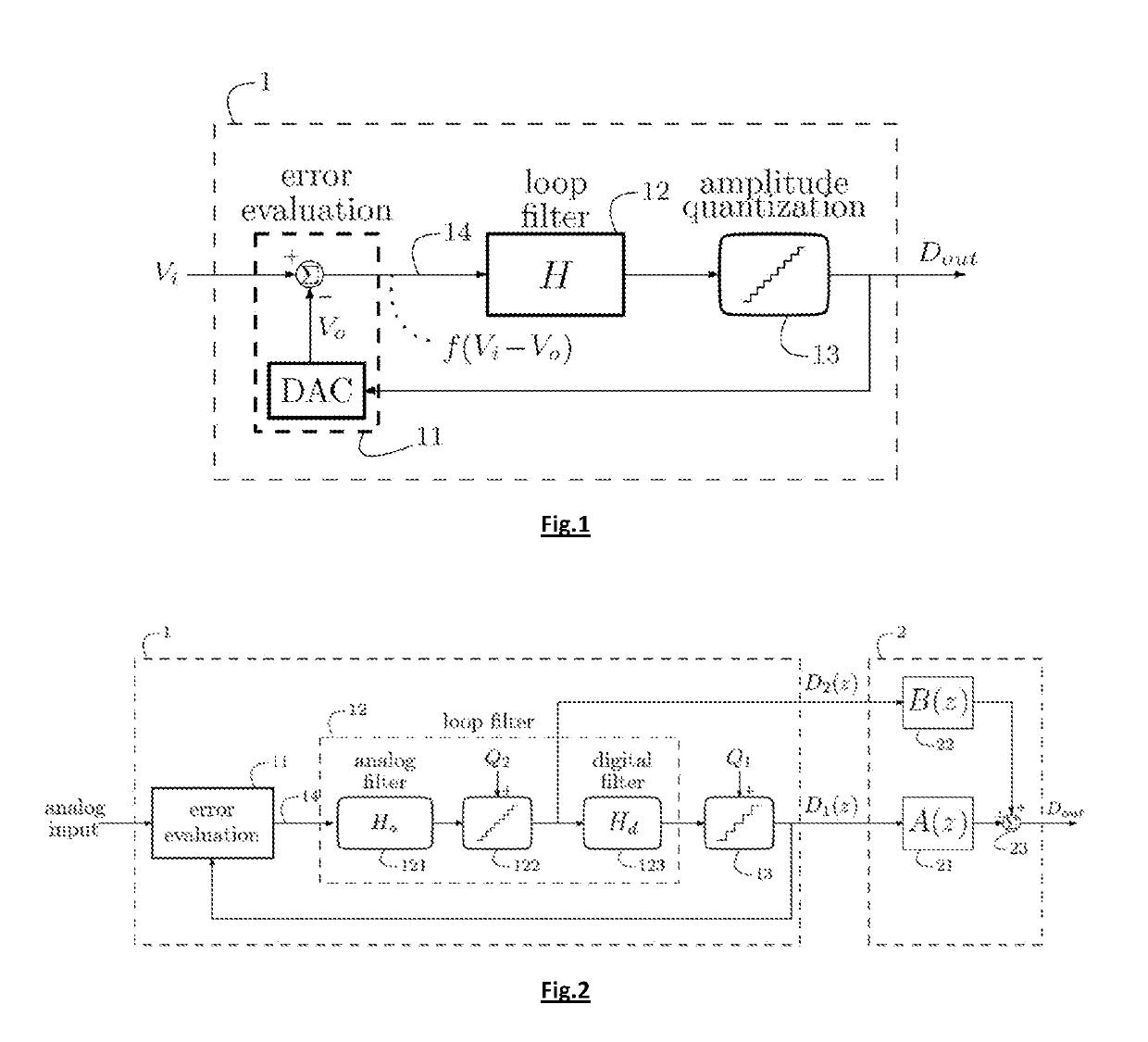
An analog-to-digital converter comprises a first quantizer arranged for yielding a first digital signal; an error signal generation block arranged for generating an error signal representative of a difference between an analog input signal and the first digital signal; an analog loop filter arranged for receiving the error signal; a second quantizer arranged for receiving an output signal of the analog loop filter and for outputting a second digital signal; a digital loop filter arranged for receiving the second digital signal and for providing an input signal to the first quantizer; and a recombiner block comprising a first recombination and a second recombination filter, and an adder circuit for adding outputs of the first and second recombination filters. The first and second recombination filters are selected to obtain an analog-to-digital converted output signal being less dependent on quantization noise caused by the first quantizer than a first digital signal.

Description

FIELD OF THE INVENTION[0001]The present invention is generally related to the field of converter circuits for converting an analog signal into a corresponding digital signal.BACKGROUND OF THE INVENTION[0002]This invention is concerned with analog-to-digital conversion, i.e. with converting an analog input signal into a corresponding digital output signal having only discrete output values that change at discrete instants in time (the sampling instants). The analog input signal may correspond to an electrical quantity, such as a voltage, a current, a charge, . . . , but also to other types of physical quantities that have an analog nature, such as a position, an angle, a phase, etc.[0003]Analog-to-digital converters are considered which contain a feedback loop. A / D converters with such a scheme are encountered for example in Sigma-Delta modulators (SDM). FIG. 1 provides an illustration. The feedback loop (1) comprises means (11) for evaluating an error between an analog input Vi and ...

Claims


Application Information

Patent Timeline
IPC IPC(8): H03M3/00
CPCH03M3/458H03M3/414H03M3/438H03M3/368H03M3/412
Inventor RAMAN, JOHANROMBOUTS, PIETER
Owner MELEXIS TECH NV
Why Eureka
Eureka Blog
Learn More