Multi-depth display apparatus

Pending Publication Date: 2019-10-17
CAMBRIDGE ENTERPRISE LTD +1
0 Cites 2 Cited by

AI-Extracted Technical Summary

Problems solved by technology

Such displays are typically limited in size and project the image at a fixed depth to the user.
Due to the limited size, the HUD may be cluttered with information that is less relevant to the user taking up real estate.
This further reduces the ef...

Method used

[0082]Alternatively, when the image generation layer is used to generate the real images 501-503, both the picture generation unit 200 and the optical diffuser 400 are in a deactivated/idle state to save power.
[0088]Advantageously in order to reduce the effect of the distortion in an aspect of the invention the windscreen distortion is corrected for...

Benefits of technology

[0027]Optionally the picture generation unit is an OLED device. OLEDs provide a flexible and compact multi-colour display.
[0028]The projection of 3-dimentional images through the imaging system enables such images to be displayed on the display screen with the appropriate varying depth so as to produce a convincing representation of a real object.
[0029]Optionally the picture generation unit, image realisation device and pr...

Abstract

An imaging system includes an image realisation device and projection optics for rendering a display image on a display screen. The image realisation device includes a first image realisation surface tilted relative to an optical axis such that a first point in a first region of the image realisation surface is at a first distance from the focal point of the projection optics and a second point in a second region of the image realisation surface is at a second different distance from the focal point of the projection optics. A first source image formed on the first region and projected through the projection optics renders the first display image on the display screen at a first apparent depth, and a second source image formed on the second region and projected through the projection optics renders the second display image on the display screen at a second apparent depth.

Application Domain

Optical elements

Technology Topic

Projection opticsImage system +5

Image

  • Multi-depth display apparatus
  • Multi-depth display apparatus
  • Multi-depth display apparatus

Examples

  • Experimental program(1)

Example

[0048]In an aspect of the invention the apparatus and the display are installed in a vehicle, such as a motor vehicle. Whilst the following description is described with reference to a head-up display (HUD) of a motor vehicle, the disclosure, and concepts described herein are applicable to other forms of HUD (for example those installed on other forms of vehicles or wearable platforms such as helmets or goggles), as well as displays in general.
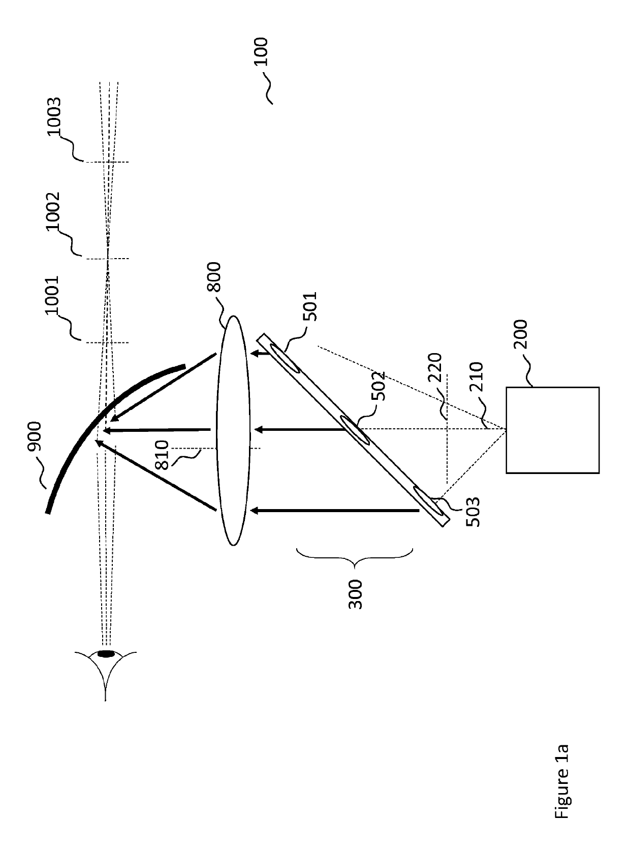
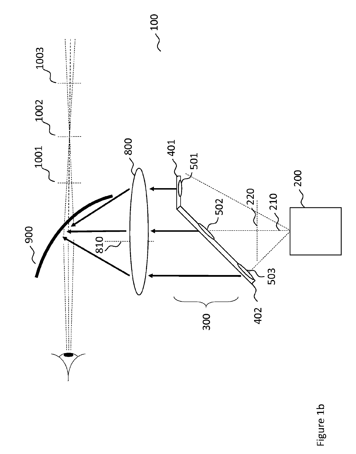
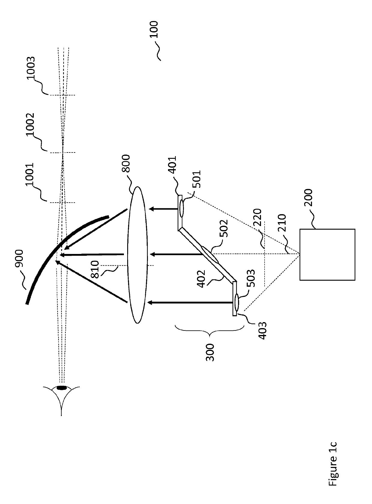
[0049]Particularly, but not exclusively, the disclosure relates to an apparatus for creating and projecting multi-dimensional 3-D augmented reality images onto a display screen, such as a windscreen if it is installed for use in a confined environment such as a vehicle which can be operated on land (on/off road or track), under or over sea, in air or space. The examples can be, but are not limited to, cars, buses, lorries, excavators, exoskeleton suit for heavy-duty tasks, motorcycles, trains, theme park rides; submarines, ships, boats, yachts, jet-skies for see vehicles; planes, gliders for air crafts, spaceships, shuttles for space crafts.
[0050]Furthermore, the technology can be installed/integrated in a mobile platform such as a driver's/operator's head/eye protection apparatus such as a helmet or goggles. Therefore, any activity, which involves wearing protective helmets/goggles, can benefit from this technology. These can be worn by, but are not limited to, motorcyclist/cyclist, skiers, astronauts, exoskeleton operators, military personnel, miners, scuba divers, construction workers. Moreover, it can be used in a standalone environment for game consoles, arcade machines and with a combination of an external 2D/3D display it can be used as a simulation platform. Also, it can be used in institutions and museums for educational and entertainment purposes.
[0051]It is also possible to use the described invention in scenarios, where a non see-through screen is present, such as a virtual reality system.
[0052]FIGS. 1a, 1b and 1c show various embodiments of an imaging system for realising images at multiple apparent depths on a display.
[0053]FIG. 1a shows an imaging system 100 made up of a picture generation unit 200 having a projection axis 210. The picture generation unit 200 projects light onto the image realisation device 300. The real images 501-503 formed in the image realisation device 300 are directed through projection optics 800 having optical axis 810 onto the screen 900 of a head-up display to form display images.
[0054]The path of the light from the picture generation unit 200, through the image realisation device 300 and the projection optics 800 and onto the screen 900 of the head-up display is referred to as the optical path. The skilled person would understand that any number of intervening reflectors/lens or other optical components may be placed along the optical path between the picture generation unit 200, the image realisation device 300 and the projection optics 800, to manipulate the optical path as necessary (for example, to minimize the overall size of the imaging system 100).
[0055]The form and functionality of the image realisation device 300 are described in further detail below with reference to FIGS. 2 and 3.
[0056]Returning to FIG. 1a, in use, the source images for example, real images 501-503 are formed in the image realisation device 300. As the image realisation device 300 is an extended surface which is tilted relative to the optical axis such that images formed on different portions of the image realisation device are at different distances from the focal point of the projection optics 800. As such each real image 501-503 results in a virtual image 1001-1003 having a different focus (or perceived depth) visible on the screen 900 of the head-up display.
[0057]Accordingly, the apparatus, due to the tilted extended surface allows for virtual images to be generated at the HUD at a desired depth by forming the image at different portions of the image realisation device 300.
[0058]In FIG. 1a the image realisation device 300 is a single extended surface which is tilted relative to the optical axis. FIGS. 1b and 1c show different embodiments of the imaging system 100 in which the image realisation device 300 comprises different shaped surfaces on which the real images 501-503 are formed.
[0059]In FIG. 1b there is shown the imaging system 100 as described with reference to FIG. 1a. In FIG. 1b the image realisation device 300 comprises a surface having a first portion 401 which is perpendicular to the optical axis and a second portion 402 which is tilted at a first angle relative to the optical axis. Whilst in FIG. 1b the first portion 401 is shown to be perpendicular to the optical axis, in further embodiments, the second portion may be at any angle relative to the optical axis, which is different to the first angle.
[0060]As shown in FIG. 1b two real images 502503 are formed on the second portion 402 of the image realisation device 300 and another real image 501 is formed on the first portion 401 of the image realisation device 300. As described above, with reference to FIG. 1a, as the real images 501-503 are formed at different distances from the focal point of the projection optics 800 they result in a virtual image 1001-1003 having a different focus (or perceived depth) visible on the screen 900 of the head-up display.
[0061]In FIG. 1c the image realisation device 300 comprises a surface having a second portion 402 which is tilted at a first angle relative to the optical axis, and first and third portions 401, 403 which are perpendicular to the optical axis. Whilst in FIG. 1c the first portion 401 and third portion 403 are shown to be perpendicular to the optical axis, in further embodiments, the second portion may be at any angle relative to the optical axis, which is different to the first angle.
[0062]FIG. 2 shows an embodiment of the image realisation device 300 of FIG. 1c in more detail. The image realisation device 300 is located between the picture generation unit 200 and the projection optics 800, with each of the image realisation device 300, picture generation unit 200 and projection optics 800 spaced apart and centred on a common axis (i.e. projection axis 210 equals optical axis 810 which together represent the optical path).
[0063]The image realisation device 300 is formed of a single, extended, image realisation surface 310. The image realisation surface 310 is an optical diffuser 400 having three regions 401, 402 and 403. Regions 401 and 403 are oriented parallel to each other and perpendicular to the projection axis 210 of the picture generation unit 200.
[0064]Region 401 is spaced apart from region 403 along both of the projection axis 210 and lateral axis 220, allowing for images projected by the picture generation means 200 to be formed at different distances along the optical axis 810 (i.e. different distances from the focal point of the projection optics 800).
[0065]Region 402 extends between potions 401 and 403 to define a complete surface, region 402 being slanted, or tilted, relative to regions 401, 403 and the projection axis 210. The slope of region 402 allows for an image to be formed across a continuous range of distances from the focal point of the projection optics 800.
[0066]Whilst the illustrated embodiment is limited to three regions arranged as described, the skilled person would appreciate that the image realisation surface 310 may be formed by any plurality of regions, having any suitable relative orientations and positioning provided the image realisation surface 310 presented to the picture generation unit 200 spanned a range of distances from the focal point of the projection optics 800.
[0067]The picture generation unit 200 is formed of a laser and a 2D scanning mirror though the skilled person would appreciate that any suitable light source and imaging means may be used provided they were capable of forming one or more images on the optical diffuser 400. Accordingly, in an embodiment the picture generation unit 200 is a holographic unit which produces computer generated holograms for forming on the image realisation surfaces. In an alternative embodiment, the picture generation unit 200 is a light field unit to produce 3-dimentional light field images for forming on the image realisation surfaces.
[0068]In an embodiment, the picture generation unit 200 further includes imaging optics for manipulating the real images 501-503 onto the relevant region of the image realisation device 300.
[0069]The projection optics 800 are formed of a Fresnel lens, though any suitable focussing optics may be employed.
[0070]In operation, the picture generation unit 200 projects a series of real images 501-503 onto the optical diffuser 400 such that a separate real image 501-503 is formed on each of the three optical diffuser regions 401-403.
[0071]Due to the arrangement of the diffuser regions 401-403 along the optical axis 810 and their differing distances from the focal point of the projection optics 800, each real image 501-503 is formed at a different distance from the focal point of the projection optics 800 such that when directed on to the screen 900 of the head-up display via the projection optics 800, each real image 501-503 appears as a virtual image 1001-1003 having a distinct level of focus (or perceived depth).
[0072]The set distance of optical diffuser regions 401 and 403 from the focal point of the projection optics 800 allows for a discrete difference in associated virtual image depth, whilst the tilted surface of optical diffuser region 402 provides a continuous change in distance from the focal point and thus a continuous change in the resulting virtual image depth. As such the tilted surface allows for the projection of the virtual image at the HUD at any number of depths by rendering the real image at the appropriate location of the tilted surface.
[0073]In an alternative embodiment, the image realisation surface 310 is continuous and slanted relative to the projection axis 210, such that the normal to the first optical diffuser surface 310 is at a constant angle.
[0074]As with optical diffuser region 402 described above, this allows the real images 501-503 to be projected at a continuous range of distances from the focal point of the projection optics 800 depending on which region of the image realisation surface 310 they are formed. This provides a continuous range of focuses/perceived depths of the resultant virtual images 1001-1003 displayed on the screen 900 of the head-up display.
[0075]FIG. 3 depicts a further embodiment in which the image realisation surface is a curved or freeform plane such that the normal of the image realisation surface continuously changes its angle relative to the projection axis 210 between different regions 401-403 of the optical diffuser 400.
[0076]In an embodiment, the optical diffuser arrangement is limited in extent along projection axis 210 such that the projected real images 501-503 are all within the focal depth of the picture generation units, allowing for each of the real images 501-503 to be sharp.
[0077]In alternative embodiment, the image realisation surface 310 is an image generation layer rather than an optical diffuser 400. In an embodiment, the image generation layer is an electroluminescent OLED, though any suitable image generation means may be employed.
[0078]The image generation layer is arranged relative to the projection optics 800 in the same manner as the optical diffuser of the earlier embodiments.
[0079]Rather than forming images projected by the picture generation unit 200, the image generation layer generates real images 501-503 by itself, which are then projected through the projection optics. This removes the need for a picture generation unit.
[0080]In a further embodiment, the image realisation device 300 is formed of both the optical diffuser 400 and the image generation layer, with the image generation layer positioned along the optical path and the optical axis 810 between the optical diffuser 400 and the projection optics 800. This provides for a system with two modes of operation, wherein each mode may be adapted to operate in different range of ambient light conditions.
[0081]In use, when the picture generation unit 200 is being employed to form images on the optical diffuser 400, the image generation layer is in a transparent, deactivated state, thereby allowing the real image 501-503 to pass through to the projection optics 800.
[0082]Alternatively, when the image generation layer is used to generate the real images 501-503, both the picture generation unit 200 and the optical diffuser 400 are in a deactivated/idle state to save power.
[0083]In an alternative embodiment, the image generation layer is positioned along the projection axis 210 between the optical diffuser 400 and the picture generation unit 200. In this embodiment, the image generation layer is once again in a transparent state when the optical diffuser 400 and picture generation unit 200 are in use.
[0084]In another mode of operation, the image generation layer is used to generate the real images 501-503 and the optical diffuser 400 transitions to a transparent state so as to allow the real images 501-503 pass to the mirror array without interference. The overlaying of the optical diffuser 400 and image generation layer in this way allows for a dual mode system without requiring a second set of projection optics 800.
[0085]FIG. 4 is a flow chart of the process for generating the image to be rendered on the screen of the head-up display.
[0086]In an aspect of the invention the apparatus generates a virtual image which is displayed on the HUD, the HUD being a windscreen of the vehicle. As is known the windscreen of a vehicle is a geometrically distorted shape i.e. it is not flat. Accordingly, an image that is projected onto the windscreen will be distorted, the level of distortion being affected by various factors such as the shape of the windscreen, and the average distance of the windscreen from the projected image.
[0087]The apparatus described herein is able to generate an image which can be presented at various depths. Whilst the generation of the images at multiple depths on the HUD provides many advantages over a flat, single depth, image the ability to correct for factors such as the curvature of the windscreen results in further improvements in terms of depth control and image manipulation.
[0088]Advantageously in order to reduce the effect of the distortion in an aspect of the invention the windscreen distortion is corrected for by the image generation unit using software to pre-distort the image such that the image rendered on the windscreen is free from any distortions created by the windscreen. Such a software based correction eliminates the need for bulky correction optics and furthermore provides a higher degree of flexibility which can adapt to different windscreens.
[0089]The images to be presented on the HUD are generated by a picture generation unit. The picture generation unit defining the image to be displayed by the HUD. By way of example the image may comprise information regarding the car conditions and further information relating to navigation.
[0090]The term picture generation unit refers to the apparatus which determines and generates the base image to be rendered on the HUD. The process described herein is applicable to any suitable form of picture generation apparatus.
[0091]The picture generation unit comprises an image source which generates the image to be displayed on the HUD. The image source in an embodiment is a light engine, or OLED display or any suitable source which generates the image to be displayed. The image source comprises a software driver configured to determine and generate the image on the image source.
[0092]The software driver comprises a component which determines the content to be displayed. The process of the generation of content is known and in an aspect is performed using known means.
[0093]The driver further comprises a distortion module, the distortion module configured to apply a distortion to the generated image, the distortion calculated such that when the image is displayed on the HUD/windscreen the image appears undistorted to the end user.
[0094]At step S102 the windscreen is modelled as a mirrored surface. At step S102 the shape and gradient of the windscreen is determined. In an embodiment, as the shape of the windscreen is typically constant for a particular make and model of a vehicle it is pre-programmed.
[0095]At step S104 the image to be displayed on the HUD is taken as reference input image. Such an image will typically change several times per second.
[0096]At step S106 the input image is separated for each colour channel of the image to create an image per colour channel.
[0097]At step S108 for each colour channel image, for each pixel of the image the position of the pixel as visualised by a viewer located at a distance away from the windscreen surface is determined. This is determined by using ray reflection in order to determine the position of the pixel based on the average distance of the input pixel (as per step S106) the reflection surface of the windscreen (as per step S102) and the average distance between the rendered image and the windscreen, the image depth.
[0098]Therefore, at step S108 the level of distortion for each colour channel image, as a result of the windscreen and the physical distances, is calculated. This results in a distorted image (with the level of distortion being dependent on the physical parameters) for each colour channel. This can be achieved by monitoring the displacements of certain pre-defined points on a distorted image and fitting them to obtain the related distortion parameters.
[0099]At step S110 the individual distorted colour channel images are combined. The combined image is the resultant pre-distortion image as the projection of the pre-distortion image will result in the input image (as per step S104) being displayed.
[0100]As such the process provides an improved methodology for ensuring that the generated image is free from distortion.
[0101]FIG. 8 illustrates a vehicle 1 comprising the apparatus 3 of FIGS. 1 to 3. The apparatus 3 may be embodied in an imaging system.

PUM

no PUM

Description & Claims & Application Information

We can also present the details of the Description, Claims and Application information to help users get a comprehensive understanding of the technical details of the patent, such as background art, summary of invention, brief description of drawings, description of embodiments, and other original content. On the other hand, users can also determine the specific scope of protection of the technology through the list of claims; as well as understand the changes in the life cycle of the technology with the presentation of the patent timeline. Login to view more.
Why Eureka
Try Eureka