Method and means to analyze thermographic data acquired during automated fiber placement

Active Publication Date: 2019-10-17
NASA
View PDF2 Cites 15 Cited by
  • Summary
  • Abstract
  • Description
  • Claims
  • Application Information

AI Technical Summary

Benefits of technology

[0016]Additionally, by taking multiple line scans after different stages of the part's fabrication, it is possible to create a timeline of the entire structure that tracks the evolution of the intended geometry and features. This is a valuable tool, since it is difficult to predict both the occurrence of tow-tape defects, and whether or not those defects will self-correct during subsequent ply layers and curing.

Problems solved by technology

These types of variations may be caused by insufficient tow / ply adhesion, tow peel up, tow misalignment, tow twist / fold, thickness variations, foreign object debris and / or other defects.

Method used


Image

  • Method and means to analyze thermographic data acquired during automated fiber placement
  • Method and means to analyze thermographic data acquired during automated fiber placement
  • Method and means to analyze thermographic data acquired during automated fiber placement

Examples


Embodiment Construction

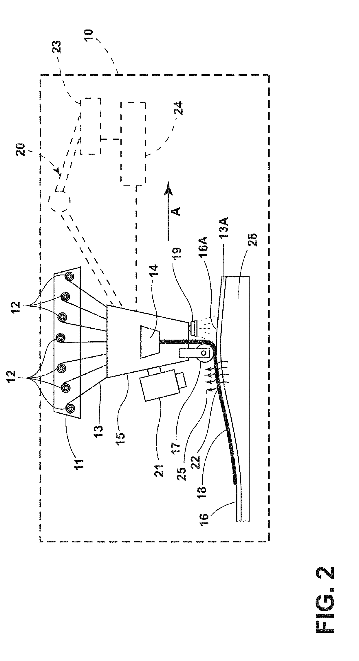
[0040]For purposes of description herein, the terms “upper,”“lower,”“right,”“left,”“rear,”“front,”“vertical,”“horizontal,” and derivatives thereof shall relate to the invention as oriented in FIG. 2. However, it is to be understood that the invention may assume various alternative orientations and step sequences, except where expressly specified to the contrary. It is also to be understood that the specific devices and processes illustrated in the attached drawings, and described in the following specification, are simply exemplary embodiments of the inventive concepts defined in the appended claims. Hence, specific dimensions and other physical characteristics relating to the embodiments disclosed herein are not to be considered as limiting, unless the claims expressly state otherwise.

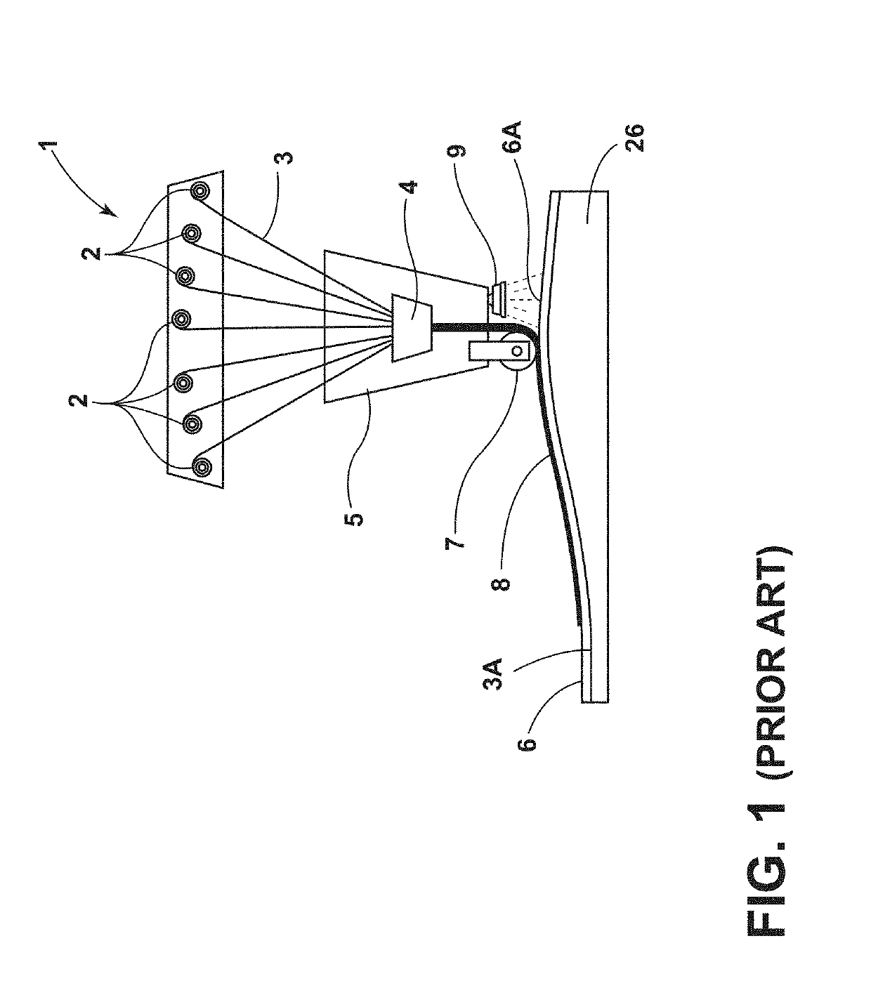
[0041]With reference to FIG. 2, an automated fiber placement (AFP) system 10 includes a fiber dispensing system 11 that feeds prepreg composite tape 13 to a movable head 15 from spools 12. The tape 13...


PUM

PropertyMeasurementUnit
timeaaaaaaaaaa
spatial dimensionsaaaaaaaaaa
time dimensionaaaaaaaaaa

Abstract

A method of detecting defects in a composite structure includes applying heat to a surface of a composite structure. Thermographic images or frames captured by a moving camera may be utilized to corm temporally aligned images that include temperature data (pixals) from a plurality of frames, wherein the pixals comprise data captured at a simple (uniform) time delay from the time at which heat was applied. The temporally aligned thermographic data for the surface region may include variations due to differences in thermal transients caused by defects in the composite structure. The variations in the thermographic data may be utilized to detect one or more defects in the composite structure.

Description

CROSS-REFERENCE TO RELATED PATENT APPLICATION[0001]This patent application claims the benefit of and priority to U.S. Provisional Patent Application No. 62 / 486,099, filed on Apr. 17, 2017, the entire contents of which is hereby incorporated by reference in its entirety.STATEMENT REGARDING FEDERALLY SPONSORED RESEARCH OR DEVELOPMENT[0002]The invention described herein was made by employees of the United States Government and may be manufactured and used by or for the Government of the United States of America for governmental purposes without the payment of any royalties thereon or therefore.BACKGROUND OF THE INVENTION[0003]Automated fiber placement (AFP) systems have been developed to deposit composite tow tape onto a substrate in a predefined manner to thereby fabricate composite structural components. Automated fiber placement uses discrete tows of carbon fibers that are pre-impregnated with epoxy resin to build up a composite part, either on a flat table or a non-planar tool. The...

Claims


Application Information

Patent Timeline
Patent Type & Authority Applications(United States)
IPC IPC(8): G06T1/00B29C70/38B29C70/54G06T7/90H04N5/33G01J5/10G01N21/88
CPCG06T2207/10048H04N5/33G01N21/8851G01J5/10B29C70/54G06T2207/30124G06T1/0014B29C70/384G01J2005/0081G06T7/90G01J2005/0077B29C70/382G06T7/0004G01J5/0022G01N2021/8472G01N2021/8444G01N25/72G01J5/047G01J5/48
Inventor JUAREZ, PETER D.GREGORY, ELIZABETH D.CRAMER, K. ELLIOTT
Owner NASA
Why Eureka
Try Eureka