
Rechargeable battery and module of the same

a rechargeable battery and module technology, applied in the direction of cell components, sustainable manufacturing/processing, final product manufacturing, etc., can solve the problems of increasing the weight increasing the space required for the constituent elements, and increasing the number of constituent elements connecting the electrode terminal and the electrode assembly, so as to reduce the weight and manufacturing cost of the rechargeable battery, simplify the structure of the electrode assembly, and reduce the number of constituent elements

Active Publication Date: 2019-10-17
SAMSUNG SDI CO LTD
View PDF0 Cites 5 Cited by
  • Summary
  • Abstract
  • Description
  • Claims
  • Application Information

AI Technical Summary

Benefits of technology

The present invention simplifies the structure of the electrode assembly around the terminal hole of the cap plate and reduces the number of constituent elements connecting the electrode assembly and the electrode terminal, thereby reducing the weight and manufacturing cost of the rechargeable battery. Additionally, the invention compresses the space between the inner surface of the cap plate and the electrode assembly, thereby reducing the cell height and improving the space utilization rate. The invention also provides strong resistance against external force and impact by using a connector with a different thickness from the thickness of one side of the internal terminal portion and the external terminal portion and attached to the molding resin material filled in the terminal hole in a wide area.

Problems solved by technology

As a result, a structure of the electrode terminal becomes complicated around the terminal hole of the cap plate, the number of constituent elements connecting the electrode terminal and the electrode assembly increases, and a space required for the constituent elements is increased.
Such structures, constituent elements, and space requirements cause the weight of the rechargeable batteries to increase, manufacturing costs to increase, cell heights to increase, and space utilization to decrease.

Method used


Image

  • Rechargeable battery and module of the same
  • Rechargeable battery and module of the same
  • Rechargeable battery and module of the same

Examples


Embodiment Construction

[0040]The present invention will be described more fully hereinafter with reference to the accompanying drawings, in which exemplary embodiments of the invention are shown. As those skilled in the art would realize, the described embodiments may be modified in various different ways, all without departing from the spirit or scope of the present invention.

[0041]The drawings and description are to be regarded as illustrative in nature and not restrictive. Like reference numerals designate like elements throughout the specification.

[0042]Throughout this specification and the claims that follow, when it is described that an element is “coupled / connected” to another element, the element may be “directly coupled / connected” to the other element or “indirectly coupled / connected” to the other element through a third element. In addition, unless explicitly described to the contrary, the word “comprise” and variations such as “comprises” or “comprising” will be understood to imply the inclusio...


PUM

PropertyMeasurementUnit
widthaaaaaaaaaa
thicknessaaaaaaaaaa
thickness t1aaaaaaaaaa

Abstract

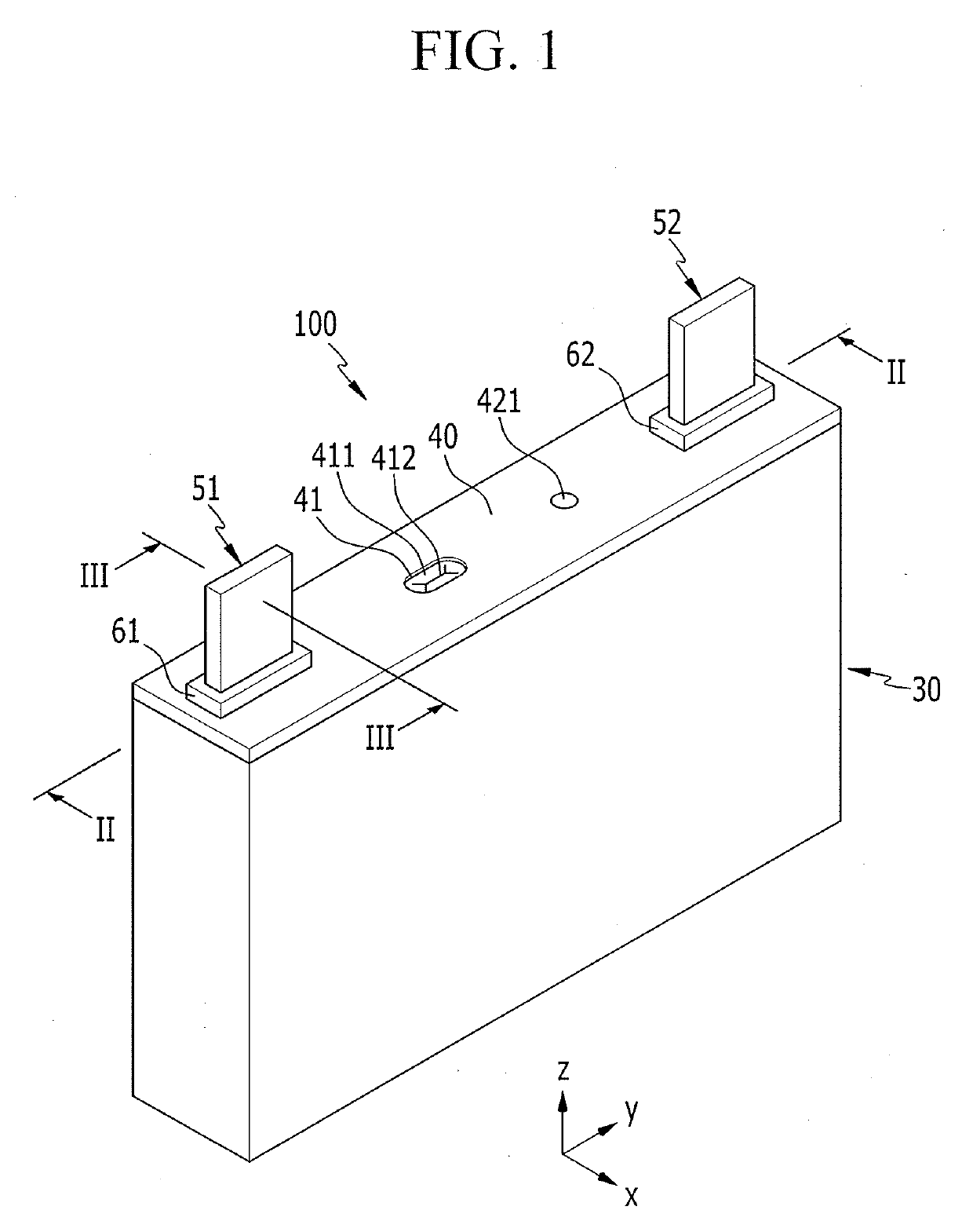
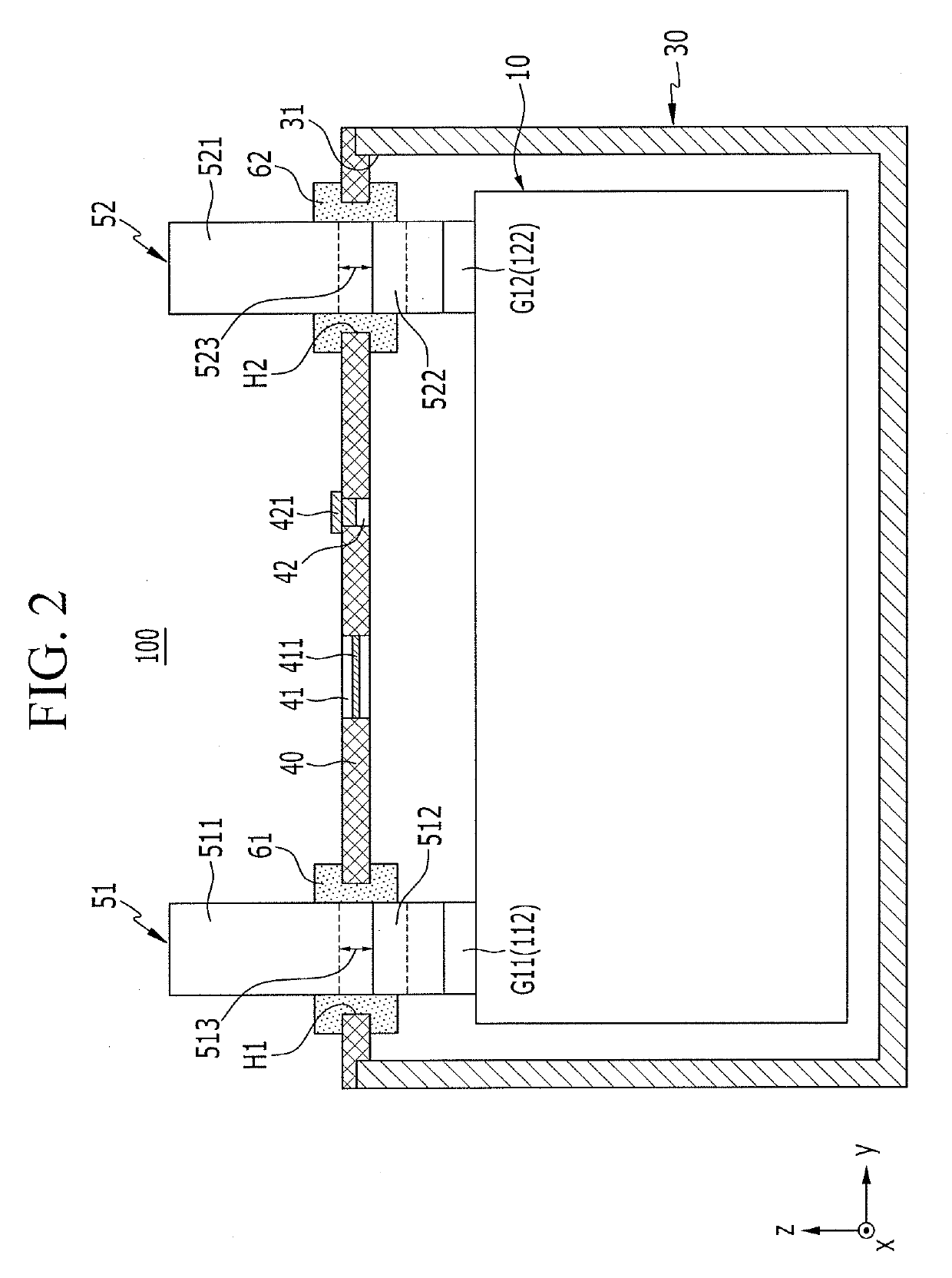
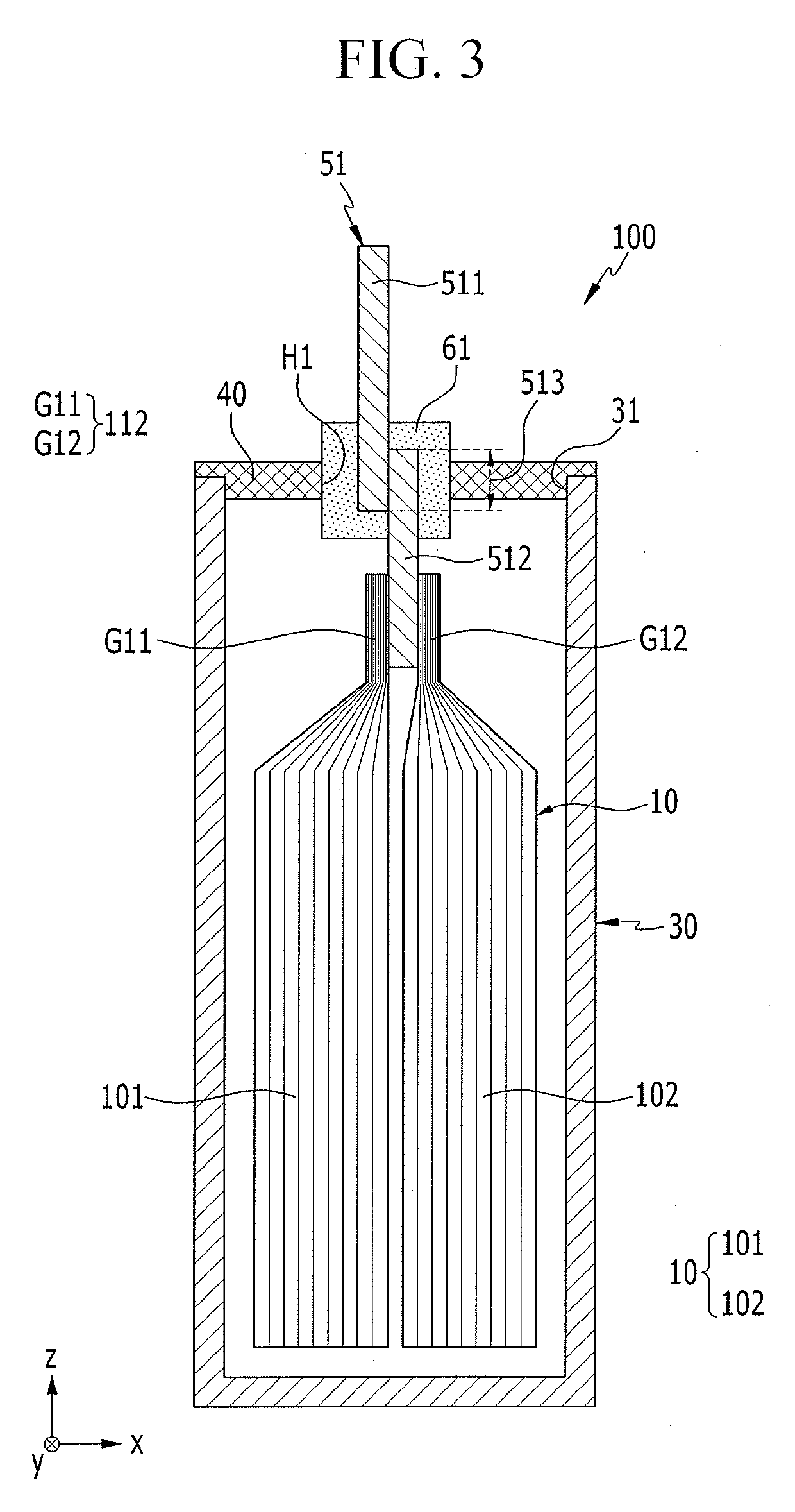
An exemplary embodiment of the present invention has been made in an effort to provide a rechargeable battery which simplifies a structure of an electrode assembly around a terminal hole of a cap plate and reduces a number of constituent elements connecting an electrode assembly and an electrode terminal. An exemplary embodiment of the present invention provides a rechargeable battery, including: an electrode assembly formed by disposing an electrode having coated regions and uncoated tabs at opposite sides of a separator; a case configured to accommodate the electrode assembly therein; a cap plate coupled to an opening of the case; and electrode terminals insert-molded into terminal holes of the cap plate to be connected to the uncoated tabs, wherein the electrode terminal includes: an external terminal portion configured to protrude outside of the cap plate; an internal terminal portion disposed within the cap plate to be connected to the uncoated tabs; and a connector configured to connect the external terminal portion and the external portion, and disposed in the terminal hole to be insulated by a molding resin material.

Description

TECHNICAL FIELD[0001]The present invention relates to a rechargeable battery and a module thereof, and more particularly, to a rechargeable battery and a module thereof, which connects a plurality of uncoated tabs drawn out from an electrode assembly to an electrode terminal.BACKGROUND ART[0002]A rechargeable battery can be repeatedly charged and discharged, unlike a primary battery. A low-capacity rechargeable battery is used for small portable electronic devices such as a mobile phone, a notebook computer, and a camcorder, and a large-capacity rechargeable battery is used as a power supply for driving a motor such as for a hybrid car.[0003]For example, a rechargeable battery includes an electrode assembly for charging and discharging, a case accommodating the electrode assembly and an electrolyte solution, a cap plate coupled to an opening of the case, and an electrode terminal that is electrically connected to the electrode assembly to draw out the electrode assembly to the outsi...

Claims


Application Information

Patent Timeline
Patent Type & Authority Applications(United States)
IPC IPC(8): H01M10/04H01M2/06H01M2/26H01M2/30H01M50/176H01M50/186H01M50/193H01M50/209H01M50/516H01M50/533H01M50/534H01M50/55H01M50/557H01M50/562
CPCH01M2/26H01M2/30H01M10/04H01M2/06H01M50/552H01M50/503H01M50/516H01M50/528H01M50/531H01M50/59H01M50/172H01M50/103H01M50/557H01M50/15H01M50/562H01M50/186H01M50/193H01M50/533H01M50/209H01M50/534H01M50/55H01M50/176Y02E60/10H01M50/54H01M50/538H01M50/543H01M50/502Y02P70/50
Inventor KIM, JOONGHUNKIM, KANGWOOKKIM, BACKGUNLEE, WOOK SU
Owner SAMSUNG SDI CO LTD
Learn More