Oscillating circuit and method for calibrating a resonant frequency of an LC tank of an injection-locked oscillator (ILO) of the oscillating circuit while stopping self-oscillation of the ILO

a technology of oscillating circuit and oscillating circuit, which is applied in the direction of diodes, instruments, amplifiers, etc., can solve the problems that ilos are generally inability to generate desirable oscillation frequencies, and achieve the effect of reducing the magnitude of negative resistan

Active Publication Date: 2019-10-17
KAIKUTEK INC
View PDF0 Cites 2 Cited by
  • Summary
  • Abstract
  • Description
  • Claims
  • Application Information

AI Technical Summary

Benefits of technology

[0005]Another embodiment of the present invention discloses a method of calibrating an oscillating circuit. The oscillating circuit comprises an injection-locked oscillator (ILO) having a Gm cell and an LC tank. A first node of the Gm cell receives a first injection signal, and a second node of the Gm cell receives a second injection signal. The first injection signal and the second injection signal are differential signals. The Gm cell provides a negative resistance between a first output end and a second output end of the Gm cell. The LC tank comprises a first inductor, a first capacitor, and a second inductor. A first end of the first inductor is coupled to the second node, and a second end of the first inductor is coupled to the first node. A first end of the first capacitor is coupled to the second node and the first end of the first inductor, and a second end of the first capacitor is coupled to the first node and the second end of the first inductor. The method comprises tuning a resonant frequency of the LC tank to a specific frequency of the first injection signal and the second injection signal; and controlling the ILO to stop self-oscillating by reducing the magnitude of the negative resistance while tuning the resonant frequency of the LC tank.

Problems solved by technology

However, due to process, voltage, and temperature (PVT) variations, ILOs are generally unable to generate desirable oscillation frequencies.

Method used


Image

  • Oscillating circuit and method for calibrating a resonant frequency of an LC tank of an injection-locked oscillator (ILO) of the oscillating circuit while stopping self-oscillation of the ILO
  • Oscillating circuit and method for calibrating a resonant frequency of an LC tank of an injection-locked oscillator (ILO) of the oscillating circuit while stopping self-oscillation of the ILO
  • Oscillating circuit and method for calibrating a resonant frequency of an LC tank of an injection-locked oscillator (ILO) of the oscillating circuit while stopping self-oscillation of the ILO

Examples


first embodiment

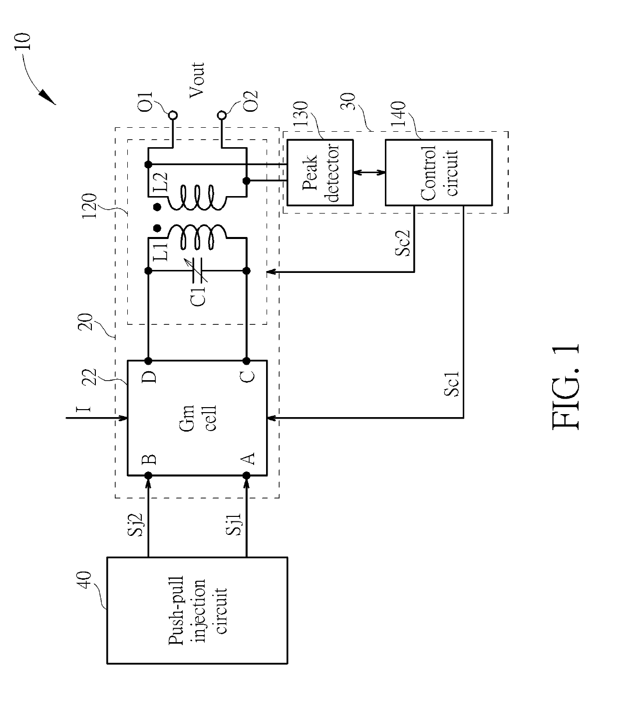
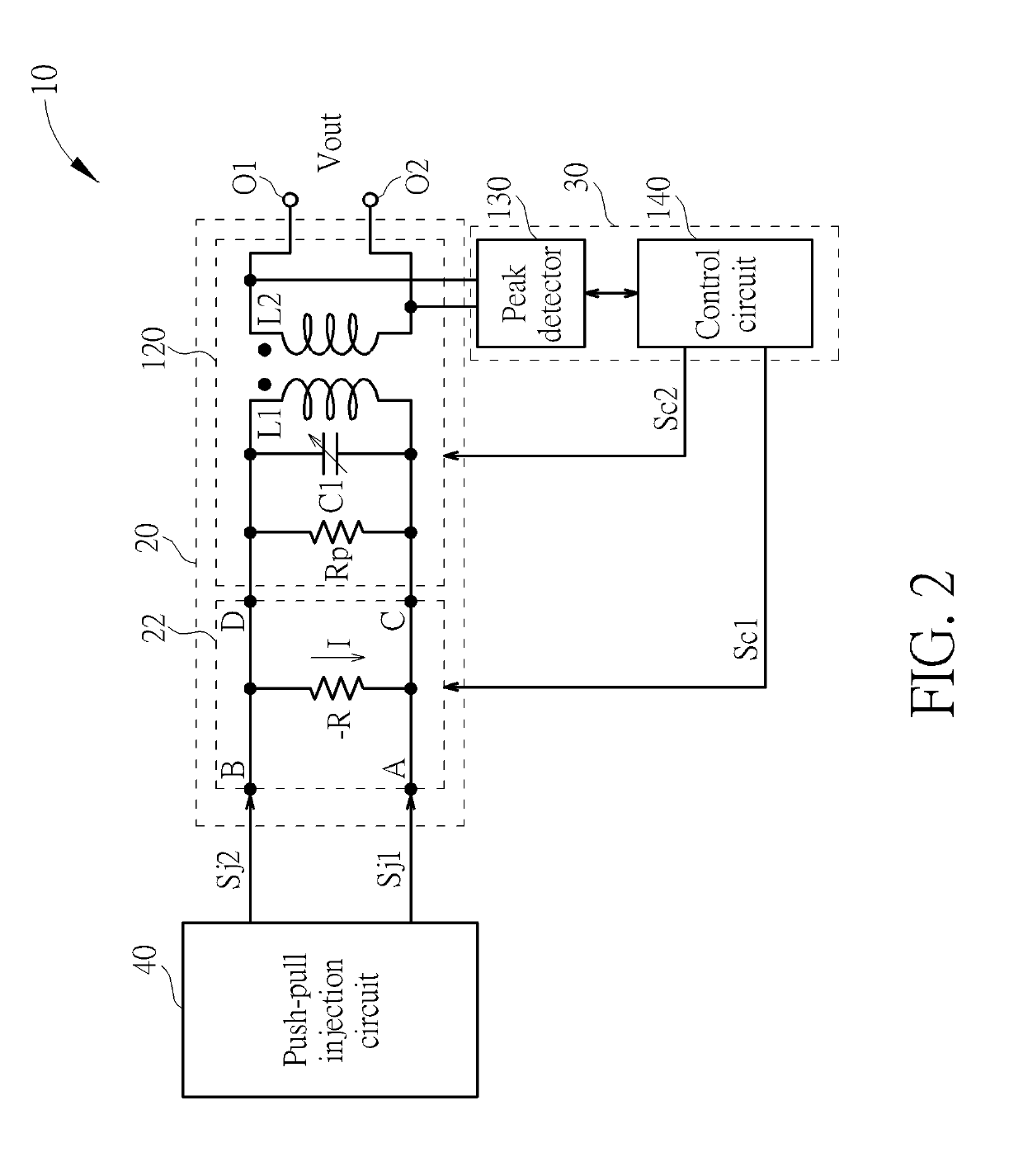
[0021]Please refer to FIG. 1 and FIG. 2. FIG. 1 is a schematic diagram of an oscillating circuit 10 according to the present invention. FIG. 2 is also a schematic diagram of the oscillating circuit 10 while a block of a Gm cell 22 of the oscillating circuit 10 shown in FIG. 1 is represented by an equivalent circuit of the Gm cell 22 in FIG. 2. The oscillating circuit 10 comprises an injection-locked oscillator (ILO) 20 and a calibration circuit 30. The ILO comprises a first node A, a second node B, the Gm cell 22, and an LC tank 120. The first node A receives a first injection signal Sj1, and the second node B receives a second injection signal Sj2. The first injection signal Sj1 and the second injection signal Sj2 are differential signals. In other words, the first injection signal Sj1 and the second injection signal Sj2 are complementary to each other. The LC tank 120 comprises a capacitor C1, a first inductor L1 and a second inductor L2. A first end of the first inductor L1 and a...

second embodiment

[0035]Please refer to FIG. 4. FIG. 4 is a circuit diagram of an oscillating circuit 100 according to the present invention. The main difference between the two oscillating circuits 10 and 100 is that the Gm cell 22 of the oscillating circuit 10 is implemented by a Gm cell 122 of the oscillating circuit 100. The Gm cell 122 is also used to provide the negative resistance −R between the first output end C and the second output end D. In the embodiment, the first output end C is directly coupled to the first node A, and the second output end D is directly coupled to the second node B. The Gm cell 122 comprises a first variable resistor Rv1, a pair 151 of P-type metal-oxide-semiconductor (PMOS) transistors Q31 and Q32, a second variable resistor Rv2, and a pair 152 of N-type metal-oxide-semiconductor (NMOS) transistors Q33 and Q34. A first end of the first variable resistor Rv1 is coupled to a first supply voltage VDD. The two PMOS transistors Q31 and Q32 are cross coupled. The source o...

third embodiment

[0039]Please refer to FIG. 5. FIG. 5 is a circuit diagram of an oscillating circuit 200 according to the present invention. The main difference between the two oscillating circuits 100 and 200 is that the oscillating circuit 200 further comprises a first push-pull injection circuit 210 and a second push-pull injection circuit 220. The first push-pull injection circuit 210 is configured to generate and output the first injection signal Sj1 to the first node A of the ILO 102, and the second push-pull injection circuit 220 is configured to generate and output the second injection signal Sj2 to the second node B of the ILO 102. Since the first injection signal Sj1 and the second injection signal Sj2 are two differential signals, a voltage level of the first node A is pushed up while a voltage level of the second node B is pulled down. The voltage level of the first node A is pulled down while the voltage level of the second node B is pushed up.

[0040]The first push-pull injection circuit...


PUM


Abstract

An oscillating circuit has an injection-locked oscillator (ILO) and a calibration circuit. The ILO has a Gm cell and an LC tank. A first node of the Gm cell receives a first injection signal, and a second node of the Gm cell receives a second injection signal. The first injection signal and the second injection signal are differential signals. The Gm cell provides a negative resistance between a first output end and a second output end of the Gm cell. When the calibration circuit tunes a resonant frequency of the LC tank of the ILO, the magnitude of the negative resistance is reduced to control the ILO to stop self-oscillating. After finishing tuning the resonant frequency of the LC tank, the calibration circuit controls the ILO to start self-oscillating by increasing the magnitude of the negative resistance.

Description

CROSS REFERENCE TO RELATED APPLICATIONS[0001]This application claims the benefit of U.S. Provisional Application No. 62 / 656,999, filed on Apr. 13, 2018, the contents of which are incorporated herein in their entirety.BACKGROUND OF THE INVENTION1. Field of the Invention[0002]The present invention relates to an oscillating circuit and a method for calibrating an oscillation frequency of the oscillating circuit, and more particularly, to an oscillating circuit and a method for calibrating a resonant frequency of an LC tank of an injection-locked oscillator (ILO) of the oscillating circuit while stopping self-oscillation of the ILO.2. Description of the Prior Art[0003]An injection-locked oscillator (ILO) is an oscillator whose oscillation frequency can be locked to a frequency of an external injection signal rather than to its inherent resonance frequency, or free-running frequency. ILOs are usually based on cross-coupled transistors and tank circuits, and have been employed for frequen...

Claims


Application Information

Patent Timeline
Patent Type & Authority Applications(United States)
IPC IPC(8): H03B5/04H03L7/099H03B5/12H03H7/06
CPCH03B5/04H03L7/099H03B2200/0074H03B5/1215H03B2200/004H03B2201/0208H03H7/06H03L7/113H03L7/16G01S7/352G01S7/40G01S7/4021G01S13/343H03F1/0205H03F1/32H03F3/10H03F3/19H03F3/45475H03F3/45636H03F2200/222H03F2200/451H03F2200/513H03F2203/45156H03F2203/45544H03F2203/45631H03L7/0816H03L7/0818H03L7/0891H04B1/18
Inventor CHEN, PANG-NINGLIN, CHEN-LUNCHEN, YING-CHIAWANG, WEI-JYUNWANG, MIKE CHUN HUNG
Owner KAIKUTEK INC
Why Eureka
Try Eureka