Optical lighting device of vehicles

a technology of optical lighting and vehicle, which is applied in the direction of semiconductor devices, lighting and heating apparatus, instruments, etc., can solve the problems of difficult production, energy consumption, and lit deficiency, and achieve the effect of simplifying the structure and downsizing the optical elements

Active Publication Date: 2019-10-24
SHUTTER PRECISION
View PDF7 Cites 3 Cited by
  • Summary
  • Abstract
  • Description
  • Claims
  • Application Information

AI Technical Summary

Benefits of technology

[0006]The objective of present invention is provide a solution downsizi

Problems solved by technology

However, after the light went through the progress of reflection and the diffusion, it generates energy consu

Method used


Image

  • Optical lighting device of vehicles
  • Optical lighting device of vehicles
  • Optical lighting device of vehicles

Examples


Embodiment Construction

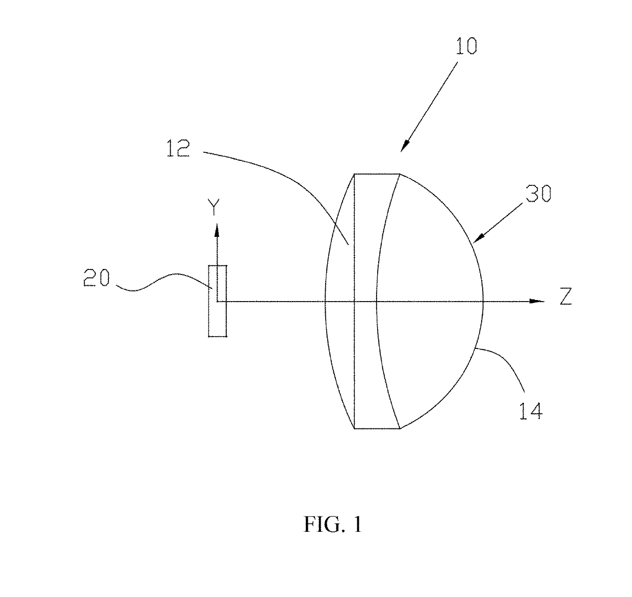
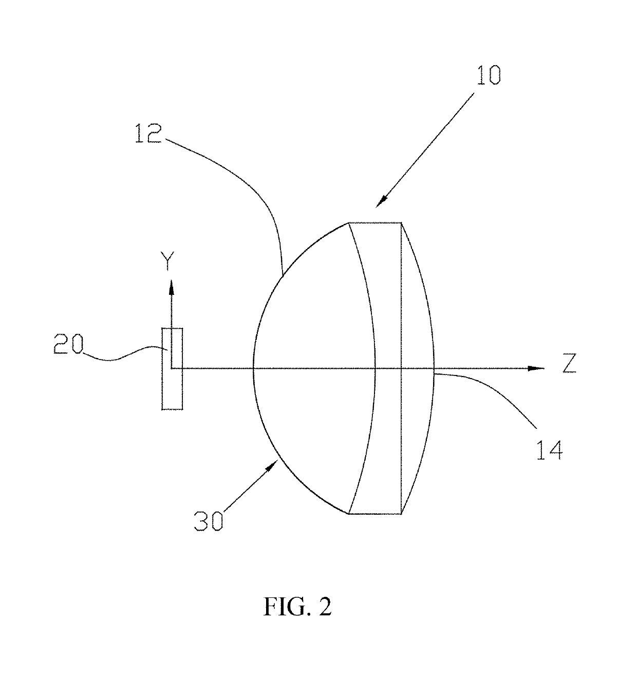
[0020]As shown in FIGS. 1 and 2, an optical lighting device includes an optical element 10, and a first light source 20 opposite to the optical element 10. The optical element 10 is a lens configured with a light incident surface 12, and a light emitting surface 14 opposite to the light incident surface 12. The first light source 20 deployed on one side of the optical element 10 opposite to the light incident surface 12.

[0021]Noticeably, at least either of the light incident surface 12 or the light emitting surface 14 forms a first anamorphic asphere 30, and the first light source 20, square in shape, projects a beam into the light incident surface 12, a primary optical mode for beam directing into a lens, and transmits out of the light emitting surface 14; to be more specifically, the beam of the first light source refracts out from a first anamorphic asphere 30.

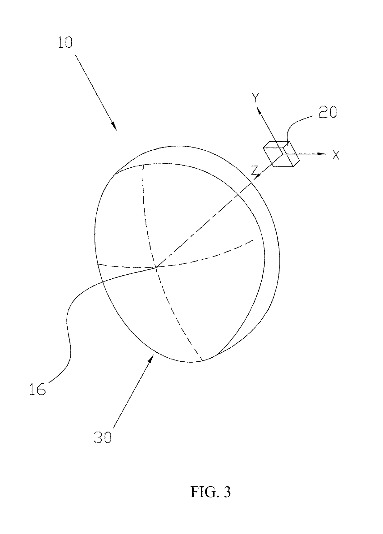
[0022]As shown in FIG. 3, the first anamorphic sphere 30 is allowed to have a plurality aspherical condensers embodied in...


PUM


Abstract

An optical lighting device includes an optical element having a light incident surface and a light emitting surface, wherein at least one first anamorphic asphere is deployed on either of the light incident surface or the light emitting surface. A first light source being square deployed on one side of the optical element and opposite to the light incident surface. The light source projects into the light incident surface, refracts by the first anamorphic asphere, transmits out of the light emitting surface and forms a predetermined light distribution area with a cut-off line on the upper fringe. Therefore, the optical lighting device has the advantage of simplified structure and high lighting efficiency.

Description

BACKGROUND OF THE INVENTION1. Field of the Invention[0001]The present invention relates to an optical lighting device and the technical field applied thereof, and more particularly, to an optical lighting device for vehicles.2. Description of the Related Art[0002]The devise of bicycle lamps usually follows the protocols: firstly, the cut-off line should be no upside flood light and at proper height avoiding the beam dazzling the vision of the drivers and the pedestrians; secondly, the light distribution area should be wide enough as to cover the vision at front of both sides.[0003]Generally, the formation of the cut-off line is formed by the emitting light which is refracted inside of the light cup deployed in front of the light source. However, after the light went through the progress of reflection and the diffusion, it generates energy consumption and lit deficiency.[0004]US20100149801A1 discloses an optical lens and light emitting diode (LED) illuminating device thereof. The pro...

Claims


Application Information

Patent Timeline
IPC IPC(8): F21S41/255F21S41/143F21S41/60G02B19/00G02B27/09F21V5/04G02B13/08
CPCF21S41/143F21V5/04F21Y2115/10F21S41/255G02B27/0955G02B13/08G02B19/0009F21Y2101/00F21S41/60F21S41/663B60Q2300/056F21W2107/13G02B19/0014G02B19/0066G02B27/0911F21S41/153
Inventor LIN, PO-CHOU
Owner SHUTTER PRECISION
Why Eureka
Try Eureka