
Heating control method and device for air conditioner

a technology for controlling methods and air conditioners, applied in heating types, lighting and heating apparatus, instruments, etc., can solve the problems of insatisfactory heating effect, inability to meet indoor requirements, slow increase of room temperature, etc., to achieve shortening time, reducing the effect of heating effect, and increasing the rate of temperature increas

Active Publication Date: 2019-10-24
QINGDAO HAIER AIR CONDITIONER GENERAL CORP LTD
View PDF0 Cites 3 Cited by
  • Summary
  • Abstract
  • Description
  • Claims
  • Application Information

AI Technical Summary

Benefits of technology

The present invention provides an air conditioner heating mode control method with an indoor temperature threshold. By selectively using a higher target frequency between outputs of the indoor temperature PID calculation and the coil temperature PID calculation, the method allows for faster warming of the room to a desired temperature and prevents output air temperature from being too low. The coil target temperature is based on the indoor temperature and is negatively correlated with the room temperature, so higher the room temperature is measured, higher the coil target temperature is set to provide more comfort to the user. Overall, the method improves the user experience and saves energy during the heating mode.

Problems solved by technology

One of the disadvantages of an air-conditioner is that if the target frequency calculated by the built-in logic is comparatively below the required level, the increasing of the room temperature will be very slow.
The room temperature could not reach the indoor requirements even it starts working for a long period.
The heating effect is far from satisfaction.

Method used


Image

  • Heating control method and device for air conditioner
  • Heating control method and device for air conditioner

Examples


Embodiment Construction

[0048]The present invention will be further described in detail below with reference to the accompanying drawings and embodiments.

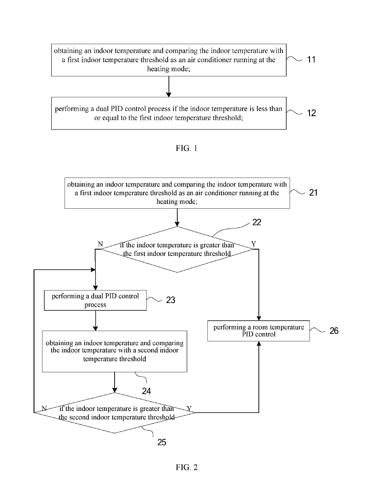
[0049]FIG. 1 is a flow chart of an air conditioner heating mode control method according to an embodiment of the present invention.

[0050]As shown in FIG. 1, the air conditioner heating mode control method includes:

[0051]Step 11: obtaining an indoor temperature and comparing the indoor temperature with a first indoor temperature threshold as an air conditioner running at the heating mode.

[0052]Wherein the indoor temperature refers to a real-time indoor temperature of the room where the indoor unit of air conditioner is arranged measured at a sampling rate as the air conditioner running at heating mode; the indoor temperature could be obtained by those means already available to the public, such as using a temperature sensor disposed at or near the air inlet of the air conditioner to detect an inlet air temperature and using the inlet air temperature as the...


PUM


Abstract

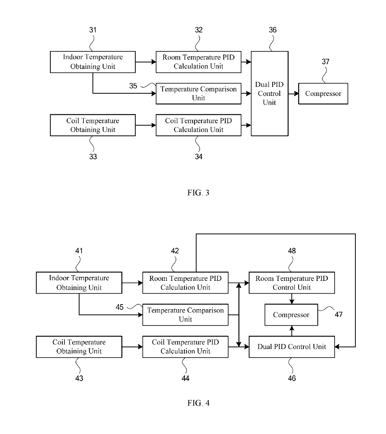
An air conditioner heating mode control method includes: Step 11: obtaining an indoor temperature and comparing the indoor temperature with a first indoor temperature threshold as an air conditioner running at the heating mode; Step 12: performing a dual PID control process if the indoor temperature is less than or equal to the first indoor temperature threshold; wherein the dual PID control process including: calculating the difference between the indoor temperature and a set indoor target temperature to obtain a indoor temperature difference; performing a PID calculation according to the indoor temperature difference to obtain a first target frequency; obtaining a coil temperature of an indoor unit heat exchanger; calculating the temperature difference between the coil temperature and a coil target temperature to obtain a coil temperature difference; performing a PID calculation according to the coil temperature difference to obtain a second target frequency; comparing the first target frequency with the second target frequency; and performing a frequency control on the compressor in which the greater one between the first target frequency and the second target frequency is used as the target frequency; wherein the coil target temperature is determined according to the indoor temperature. The present invention also discloses an air conditioner heating mode control device.

Description

FIELD OF THE INVENTION[0001]The present invention relates to the field of air conditioning technology, and more particularly to the control of an air conditioner, and more particularly to an air conditioner heating control method and a control device.DESCRIPTION OF THE RELATED ART[0002]An air conditioner unit helps to regulate the temperature of a room during cold weather. Some units even play an important role in those places where no heating systems are provided or in these days when the central heating system finishes its annual working but the weather is still cold.[0003]The heating operation logic of the air-conditioner is fully built-in inside the system. The system gets inputs from the user (e.g. desired comfort temperature) and from the surroundings (e.g. real-time indoor temperature), and according to the difference between the desired comfort temperature and the real-time indoor temperature it implements its logic to calculate a target frequency of the compressor for getti...

Claims


Application Information

Patent Timeline
Patent Type & Authority Applications(United States)
IPC IPC(8): F24F11/30F24F11/83F24F11/64G05B6/02
CPCF24F2140/20F24F2110/12G05B6/02F25B2400/077F24F11/30F24F11/64F24F2110/10F24F11/83F24F2110/00F25B49/022F25B2500/26F25B2600/0253F25B2700/2104Y02B30/70
Inventor LIU, JUKEXU, BEIBEIXU, GUOJING
Owner QINGDAO HAIER AIR CONDITIONER GENERAL CORP LTD
Learn More