
System and Method for Mapping Arrhythmic Driver Sites

a technology of driver sites and systems, applied in the field of electrophysiology mapping, can solve problems such as complex accuracy in locating arrhythmic foci, affecting timing measurements, and affecting electrogram shape changes

Active Publication Date: 2019-10-31
ST JUDE MEDICAL CARDILOGY DIV INC
View PDF0 Cites 9 Cited by
  • Summary
  • Abstract
  • Description
  • Claims
  • Application Information

AI Technical Summary

Benefits of technology

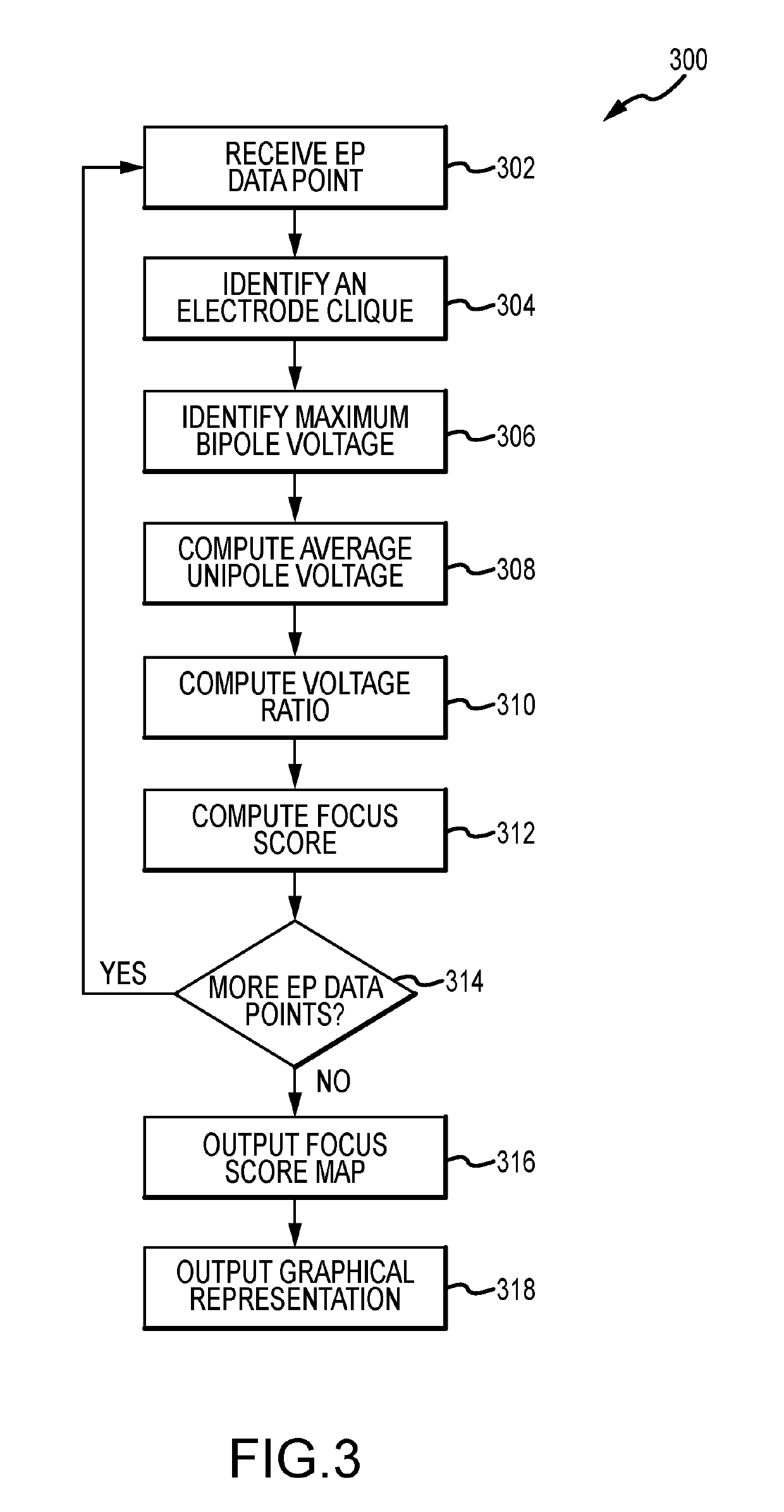
The patent describes a method for mapping arrhythmic foci in the heart using a multi-dimensional catheter. The method involves identifying a clique of three or more electrodes and computing a focus score for each location in the heart where an electrophysiology data point is collected. The focus score is based on the ratio of the computed average unipolar voltage to the maximum bipolar voltage for the clique of electrodes. The method can be used to identify the location of arrhythmic foci and can also output a graphical representation of the focus score map on a three-dimensional anatomical model. The technical effect of the patent is to provide a more accurate and reliable method for mapping arrhythmic foci in the heart.

Problems solved by technology

Accurately locating arrhythmic foci, however, can be complicated.
Timing measurements, however, can be impacted by changes in electrogram shape.

Method used


Image

  • System and Method for Mapping Arrhythmic Driver Sites
  • System and Method for Mapping Arrhythmic Driver Sites
  • System and Method for Mapping Arrhythmic Driver Sites

Examples


Embodiment Construction

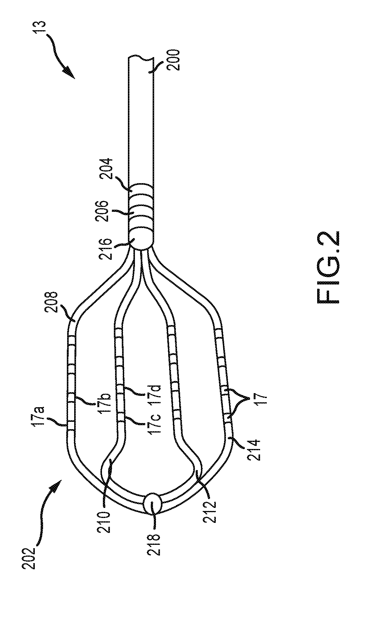
[0031]The instant disclosure provides systems, apparatuses, and methods for the creation of electrophysiology maps (e.g., electrocardiographic maps) that provide information regarding cardiac activity. Certain embodiments of the disclosure will be explained with reference to the use of a high density grid (“HD”) grid catheter, such as the Advisor™ HD grid mapping catheter from Abbott Laboratories, to create electrophysiology maps, and in particular to create maps of arrhythmic foci. Aspects of the disclosure will be described in detail herein in the context of a cardiac mapping procedure carried out using an electrophysiology mapping system (e.g., using an electroanatomical mapping system such as the EnSite Precision™ cardiac mapping system from Abbott Laboratories).

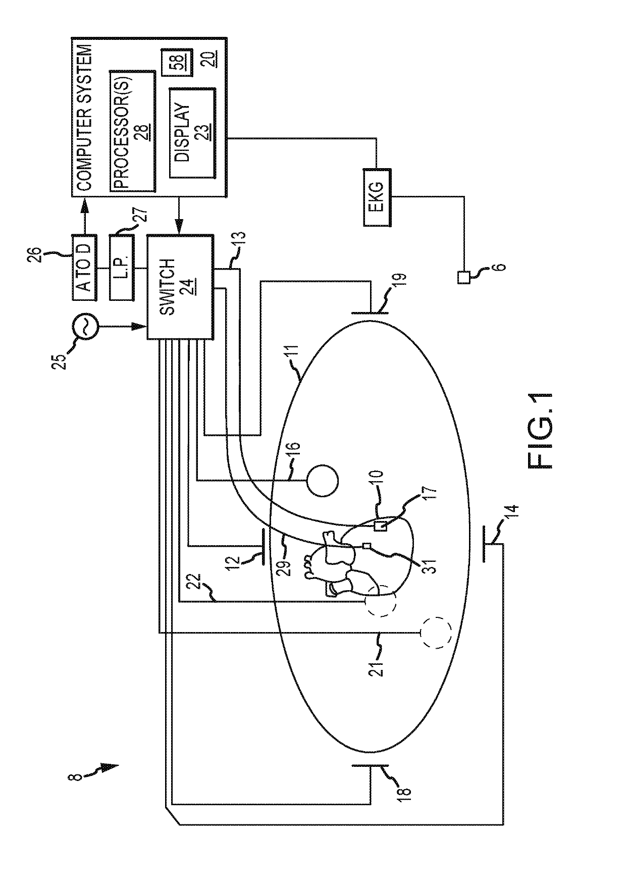
[0032]FIG. 1 shows a schematic diagram of an exemplary electroanatomical mapping system 8 for conducting cardiac electrophysiology studies by navigating a cardiac catheter and measuring electrical activity occurring in a...


PUM


Abstract

Arrhythmic foci and other driver sites can be mapped using a multi-dimensional catheter. For instance, using a clique of three or more electrodes on the multi-dimensional catheter, an electroanatomical mapping system can identify a maximum bipolar voltage and an average unipolar voltage. The ratio of the average unipolar voltage to the maximum bipolar voltage can be interpreted as an indication of whether a cardiac location is an arrhythmic focus. Alternatively, an evaluation region can be defined about location in the patient's heart. The evaluation includes a plurality of rods, each associated with a respective E-field loop having a respective maximum and minimum amplitude bipole axes, with the rods being defined by the maximum amplitude bipole axes. For a sufficient number of rods within the evaluation region, a focus score for the evaluation region can be computed to reflect rod orientation consistency within the evaluation region.

Description

CROSS-REFERENCE TO RELATED APPLICATIONS[0001]This application claims the benefit of U.S. provisional application No. 62 / 663,193, filed 26 Apr. 2018, which is hereby incorporated by reference as though fully set forth herein.BACKGROUND[0002]The present disclosure relates generally to electrophysiological mapping, such as may be performed in cardiac diagnostic and therapeutic procedures. In particular, the present disclosure relates to systems, apparatuses, and methods for mapping arrhythmic driver sites, such as arrhythmic foci.[0003]Among the mechanisms believed to initiate and maintain atrial fibrillation (“AF”) is the existence of localized drivers from which activation waves spread out, collide with one another, and produce the chaotic electrograms that can accompany AF (referred to herein as “arrhythmic foci”). It is believed that targeted ablation of these foci, while avoiding collateral damage to nearby structures such as the phrenic nerve, will terminate and prevent AF from r...

Claims


Application Information

Patent Timeline
IPC IPC(8): A61B5/042A61B5/0452A61B5/00
CPCA61B5/0452A61B5/6858A61B2562/0209A61B2562/043A61B5/0422A61B5/0538A61B5/72A61B5/287A61B5/349
Inventor DENO, DON CURTISKIM, STEVEGOKSU, FIKRIHARTLEY, THOMAS
Owner ST JUDE MEDICAL CARDILOGY DIV INC
Learn More