
Surgery assisting apparatus, method of controlling the same, storage medium, and surgery assisting system

a technology of surgery and assisting equipment, applied in the field of surgery assisting equipment, a method of controlling the same, storage media, and surgery assisting system, can solve the problems of affecting the control of the robot arm, accumulating measurement errors called drift errors, and a technique proposed in japanese patent laid-out, so as to suppress the influence of measurement errors

Active Publication Date: 2019-10-31
A TRACTION INC
View PDF0 Cites 9 Cited by
  • Summary
  • Abstract
  • Description
  • Claims
  • Application Information

AI Technical Summary

Benefits of technology

The present invention allows for intuitive control of a mechanically controlled surgical tool while reducing the impact of measurement errors. This means that surgeons can more easily and accurately control the position of the tool, which can improve the precision of surgical procedures.

Problems solved by technology

Unfortunately, the technique proposed in Japanese Patent Laid-Open No. 2003-127076 is expensive because the 6-degree-of-freedom posture must be obtained, and a measurement error for each degree of freedom sometimes largely affects the control of the robot arm.
Also, when measuring the movement of a surgical tool to be manipulated by using the inertia sensor as disclosed in the technique proposed by Japanese Patent Laid-Open No. 2007-301378, measurement errors called drift errors are actually accumulated, and the measurement results deviate from the actual positions.
That is, if the measurement errors are accumulated in the measurement results for the surgical tool, the action of the robot arm becomes unnatural.

Method used


Image

  • Surgery assisting apparatus, method of controlling the same, storage medium, and surgery assisting system
  • Surgery assisting apparatus, method of controlling the same, storage medium, and surgery assisting system
  • Surgery assisting apparatus, method of controlling the same, storage medium, and surgery assisting system

Examples


Embodiment Construction

[0027]Exemplary embodiments of the present invention will be explained in detail below with reference to the accompanying drawings. Note that in the following explanation, a case in which the posture of a surgical tool is simply measured or controlled sometimes includes a case in which the position of a specific portion of the surgical tool is measured or the specific portion of the surgical tool is controlled to another position.

[0028](Configuration of Surgery Assisting System)

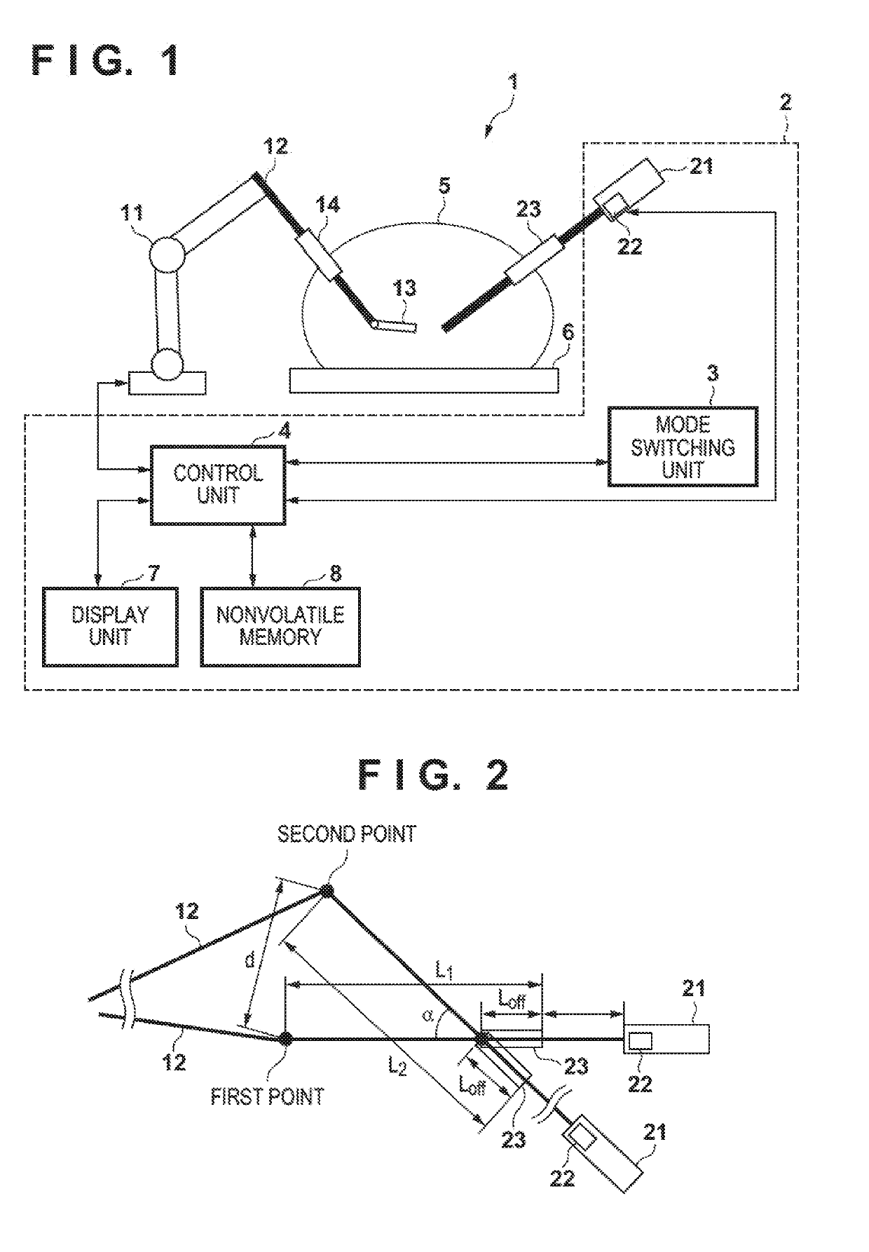
[0029]FIG. 1 is a view showing a functional configuration example of a surgery assisting system 1 according to an embodiment. Note that one or more functional blocks shown in FIG. 1 can be implemented by hardware such as an ASIC or a PLA (Programmable Logic Array), and can also be implemented by a programmable processor such as a CPU or an MPU by executing software. It is also possible to implement one or more functional blocks by combining software and hardware. In the following explanation, therefore, even ...


PUM


Abstract

A surgery assisting apparatus for controlling a posture of a first surgical tool to be inserted into a body cavity and mechanically driven, by using a second surgical tool to be inserted into the body cavity, comprises: a mode switch configured to switch a first mode and a second mode, the second surgical tool being used to control the first surgical tool in the second mode; one or more sensors configured to measure an angle and depth of insertion of a shaft of the second surgical tool into the body cavity; and at least one memory and at least one processor which function as a computing unit configured to determine a target position of a control point that is a point for specifying the posture of the first surgical tool in order to control the posture of the first surgical tool.

Description

CROSS-REFERENCE TO RELATED APPLICATIONS[0001]This application is a continuation of International Patent Application No. PCT / JP2017 / 020699 filed on Jun. 2, 2017, which claims priority to and the benefit of Japanese Patent Application No. 2017-004566 filed on Jan. 13, 2017, the entire disclosures of which are incorporated herein by reference.BACKGROUND OF THE INVENTIONField of the Invention[0002]The present invention relates to a surgery assisting apparatus, a method of controlling the same, a storage medium, and a surgery assisting system.Description of the Related Art[0003]A laparoscopic surgery by which a plurality of small-diameter holes are formed in the abdominal wall and an operator performs a surgery by inserting medical tools such as a surgical tool and an endoscope held in his or her hands into the body cavity through these holes is known. This laparoscopic surgery is generally performed such that a scopist who manipulates a laparoscope and an assistant who, for example, pul...

Claims


Application Information

Patent Timeline
IPC IPC(8): A61B34/32B25J13/08
CPCA61B2090/062A61B2034/302A61B2090/067A61B34/32A61B2034/2055B25J13/088B25J13/08A61B34/30A61B34/20A61B34/70A61B2034/2068B25J9/1656B25J9/1689
Inventor ANDO, TAKEHIROMIYAMOTO, HIROYUKIAWANO, KEITASUGIURA, YOSHIHIDE
Owner A TRACTION INC
Learn More