Accumulations of snow that slide off roofs can
cause injury to people or damage to property there-below due to the weight of the snow, the speed at which the snow falls, and the unpredictability of when and how much snow will slide off the roof.
Further, these types of buildings commonly also have irregular heating patterns.
These irregular heating patterns can lead to irregular melting patterns of snow on the roof.
Irregular melting patterns can lead to unpredictable time and places that snow slides off of the roof.
Even further, there may be many people unfamiliar with the configuration and possible dangers of the building, such as independent trucking operators.
The combination of the unpredictable melting patterns and the people unfamiliar with the melting patterns leads to risks of
possible injury to people and equipment.
Similarly, many homes, residences, cabins, ski condos, recreational properties, and resorts in snowy locales also have planar
metal roofs, and are subject to similar issues.
For example, many homes have
wood burning stoves or similar heating apparatus, which lead to irregular heating patterns.
Again, this leads to an irregular heating pattern between the home and the covered area.
In addition, the nature of these types of buildings, in that they may not be occupied regularly, leads to similar risks.
Further, children, animals, or even adults who are not aware of the possibility of sliding snow may be in danger of injury.
Again, the combination of the unpredictable melting patterns and the people unfamiliar with the melting patterns leads to risks of
possible injury to people and equipment.
In locations that receive significant amounts of snow, there is also significant amounts of freezing.
Therefore, ice dams or other accumulations of snow and ice may block gutters in these locations and lead to ice ridges on and along portions of the roof.
Therefore, accessing these gutters to service the gutters and / or to remove ice dams is difficult and potentially dangerous, and the sliding of accumulations of snow may damage the gutters and even tear the gutters from the roof
eaves causing substantial damage.
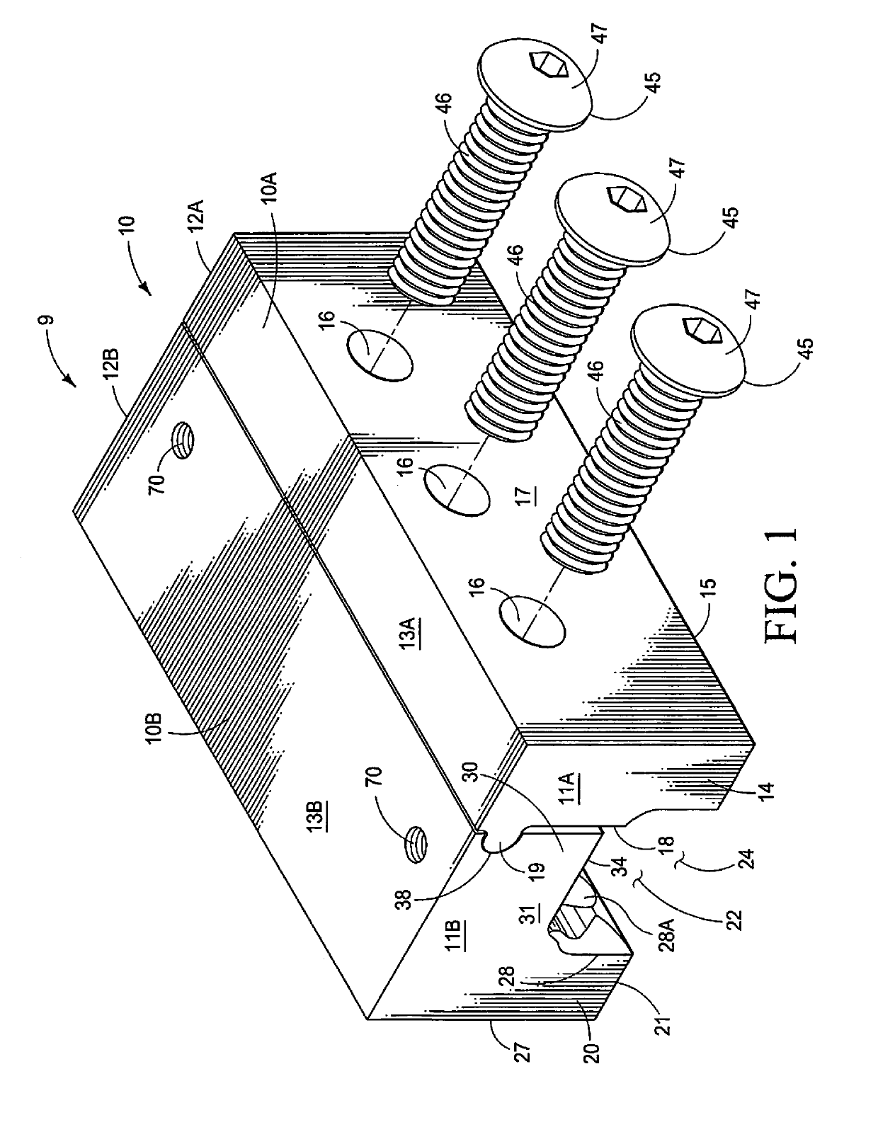
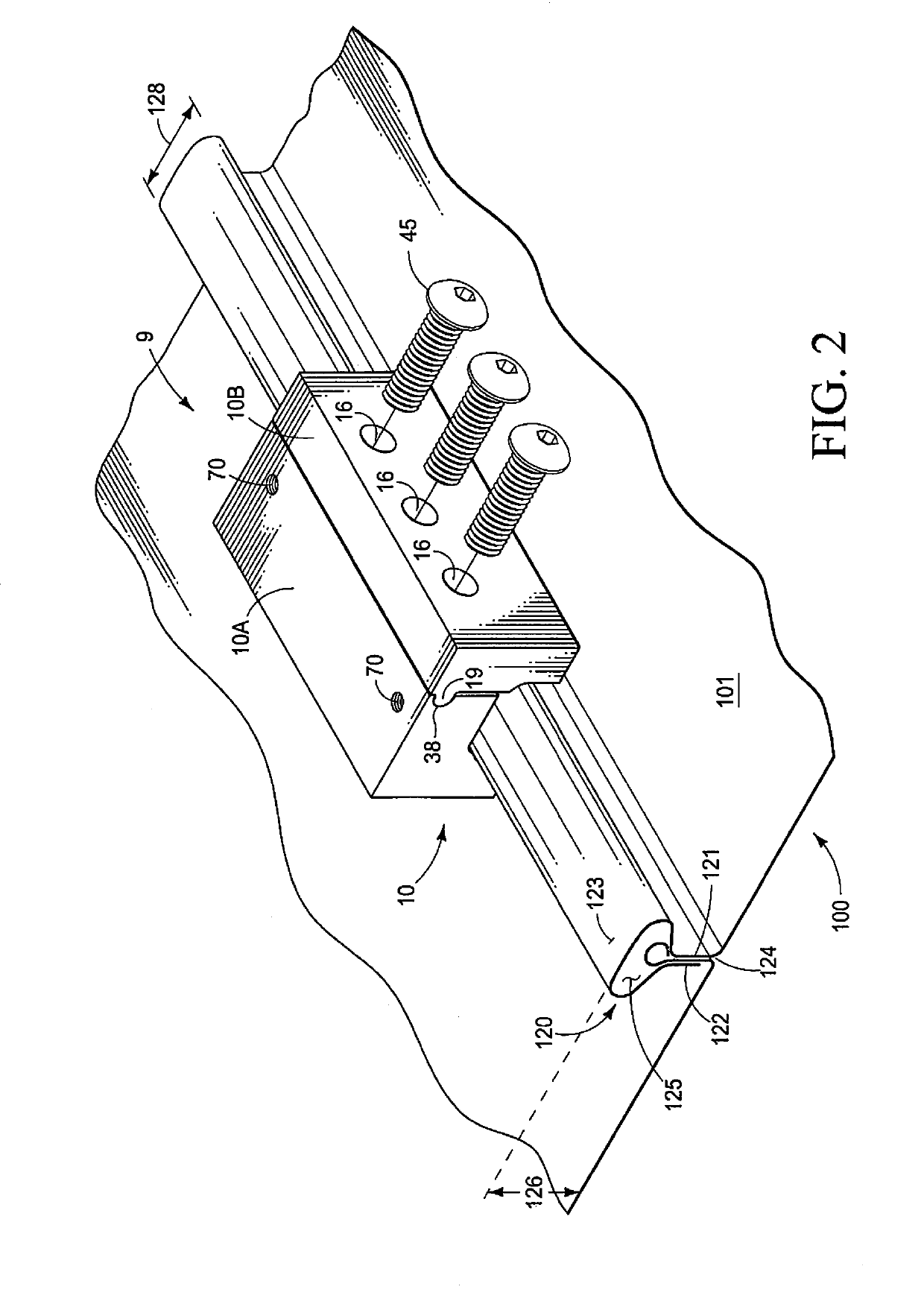
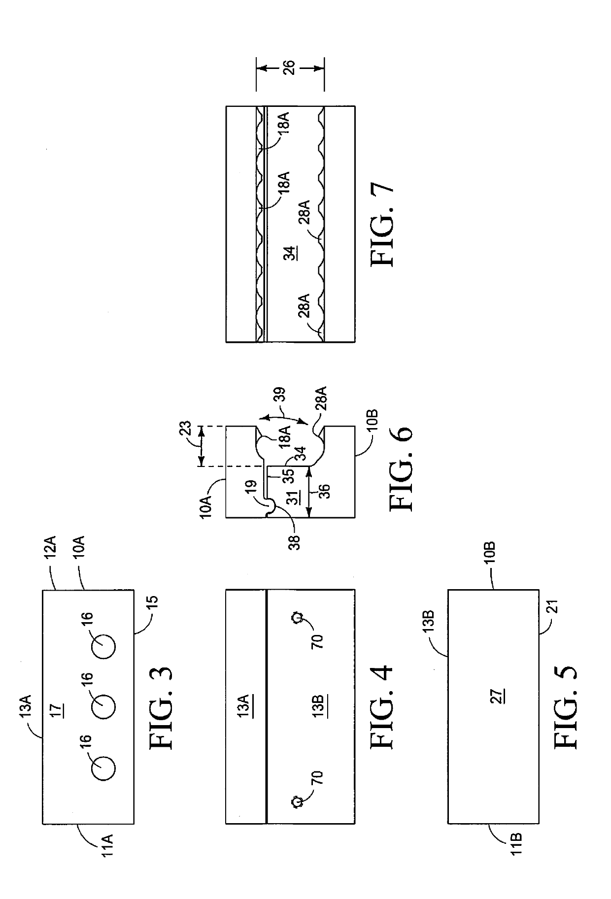
Such a standing seam configuration (T-shaped) provides material benefits over other types of standing seams, (such as, but not limited to, being substantially self-locking) but this T-shape configuration has also proven to be a difficult configuration for attaching snow brakes, especially when there is a desire to not penetrate, or otherwise form holes in the roof surface which may provide access for water leaks and the like.
However, like any roof, maintaining the integrity of the roof is critical.
Leaks created by any holes in a roof can cause a myriad of problems, from mold to ruined structure and contents.

