Light Deflector and Light Deflector Control Device
- Summary
- Abstract
- Description
- Claims
- Application Information
AI Technical Summary
Benefits of technology
Problems solved by technology
Method used
Image

Examples
first embodiment
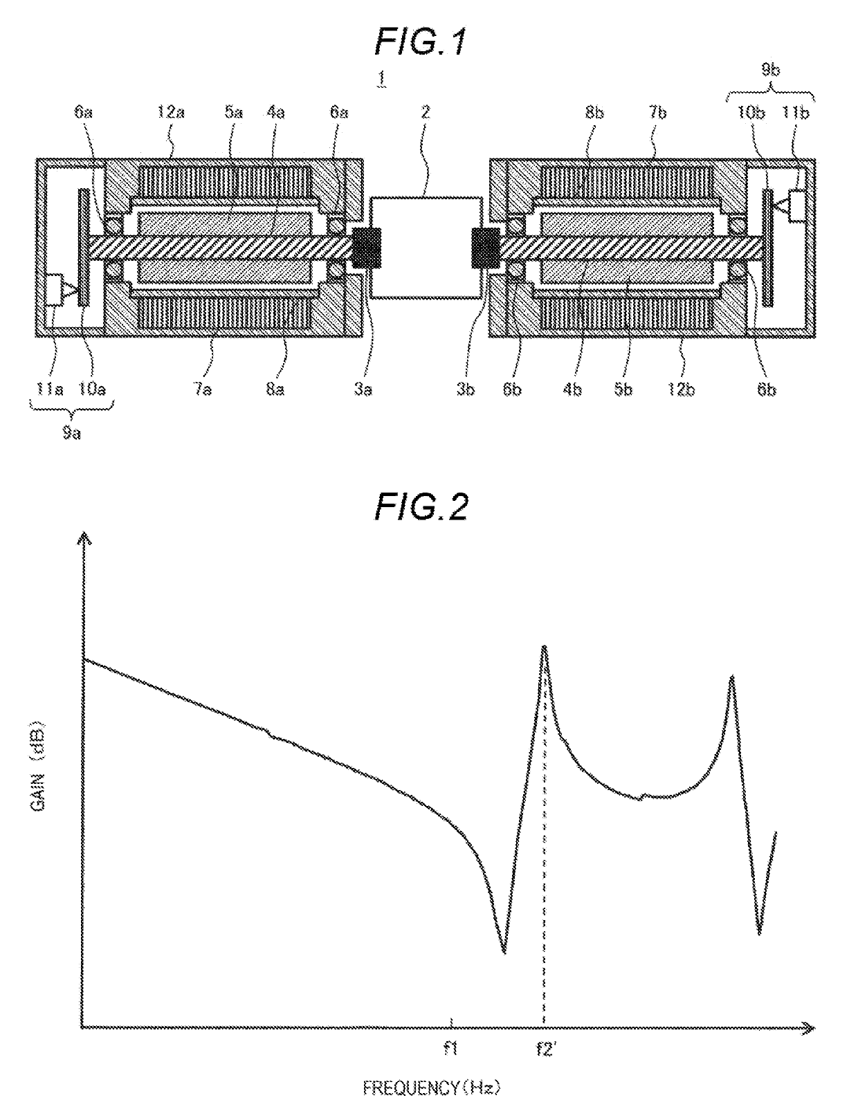
[0022]FIG. 1 is a cross-sectional view illustrating key parts of a galvano type light deflector 1 of a first embodiment. The galvano type light deflector 100 in the related art illustrated in FIG. 7 is configured such that one end of the reflector 2 is gripped by the gripper 3, and this gripper 3 is rotatably driven by the oscillation type electromagnetic actuator. The galvano type light deflector 1 of the present embodiment is configured such that opposite ends of the reflector 2 are gripped by grippers 3a and 3b, and these grippers 3a and 3b are rotatably driven in the same direction by a pair of oscillation type electromagnetic actuators. Hereinafter, a sign a is given to each component of the actuator for the gripper 3a, and a sign b is given to each component of the actuator for the gripper 3b. In addition, coils 8a and 3b are connected in series such that torques generated by two drivers when a drive current flows become the same direction.
[0023]Next, effects of the present em...
second embodiment
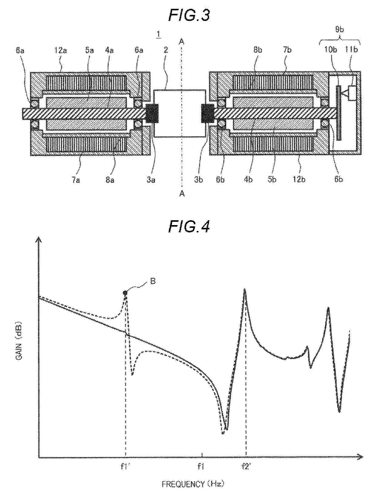
[0030]FIG. 3 is a cross-sectional view illustrating key parts of the galvano type light deflector 1 according to a second embodiment. A duplicate description of the features common between the first embodiment and the second embodiment will be omitted.
[0031]In comparison with the galvano type light deflector 1 of the first embodiment illustrated in FIG. 1, the present embodiment is different in that there is one angle detector 9, inertia (JR) around the rotating shaft 4 on the right side of line A-A passing the center of the reflector 2 is greater than inertia (JL) on the left side thereof, and a torque constant (TR) of the right driver is greater than a torque constant (TL) of the left driver. As an example, an example in which JL:JR=1.0:1.1, and TL:TR=1.0:1.1 will be described below.
[0032]A dotted line of FIG. 4 indicates the frequency response characteristic from the scanning amount (approximately equal to a drive current) to the angle detection signal when the left and right tor...
third embodiment
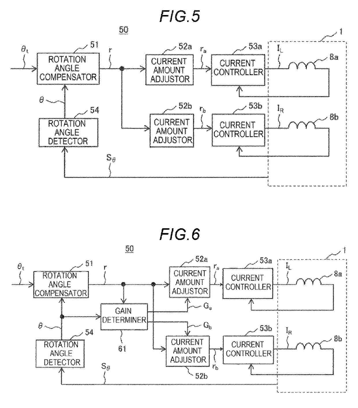
[0039]FIG. 5 is a control block diagram of a control device 50 of a galvano type light deflector 1 according to a third embodiment. A duplicate description of the features common between the embodiment and the third embodiment will be omitted. An arithmetic device such as CPU executes a program loaded on a storage device such as a semiconductor memory, whereby each function (to be described below) of the control device 50 is realized. However, this well-known technology will be described below while being appropriately omitted.
[0040]The control device 50 of the present embodiment is characterized by having current amount adjusters 52a and 52b that are provided across the reflector 2 and can independently adjust magnitudes of drive currents I supplied to the two drivers for each of the drivers. Here, in the galvano type light deflector 1 of the present embodiment, inertia around the rotating shaft 4 on the right side of the line A-A passing the center of the reflector 2 is greater th...
PUM
 Abstract
Description
Claims
Application Information
 - R&D
- Intellectual Property
- Life Sciences
- Materials
- Tech Scout
- Unparalleled Data Quality
- Higher Quality Content
- 60% Fewer Hallucinations
Browse by: Latest US Patents, China's latest patents, Technical Efficacy Thesaurus, Application Domain, Technology Topic, Popular Technical Reports.
© 2025 PatSnap. All rights reserved.Legal|Privacy policy|Modern Slavery Act Transparency Statement|Sitemap|About US| Contact US: help@patsnap.com