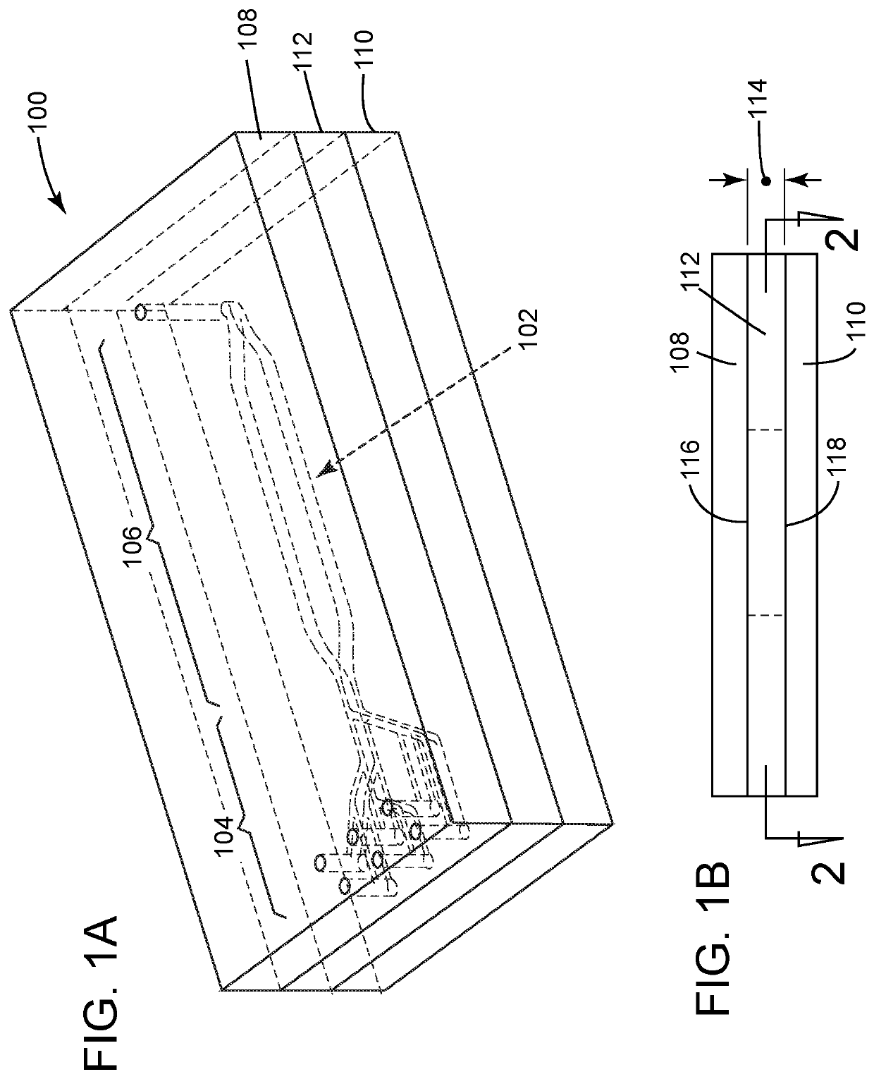
Flow cell with integrated manifold

a flow cell and integrated technology, applied in the field of flow cells with integrated manifolds, can solve the problems of large amount of reagent flushing volume, difficult to flush reagent out, and high cost of reagents used in such sequenced chemical reactions, so as to reduce the total flush volume, reduce the dead area of reagent flow, and reduce the effect of total flush volum

Active Publication Date: 2019-11-07
ILLUMINA INC
View PDF0 Cites 3 Cited by
  • Summary
  • Abstract
  • Description
  • Claims
  • Application Information

AI Technical Summary

Benefits of technology

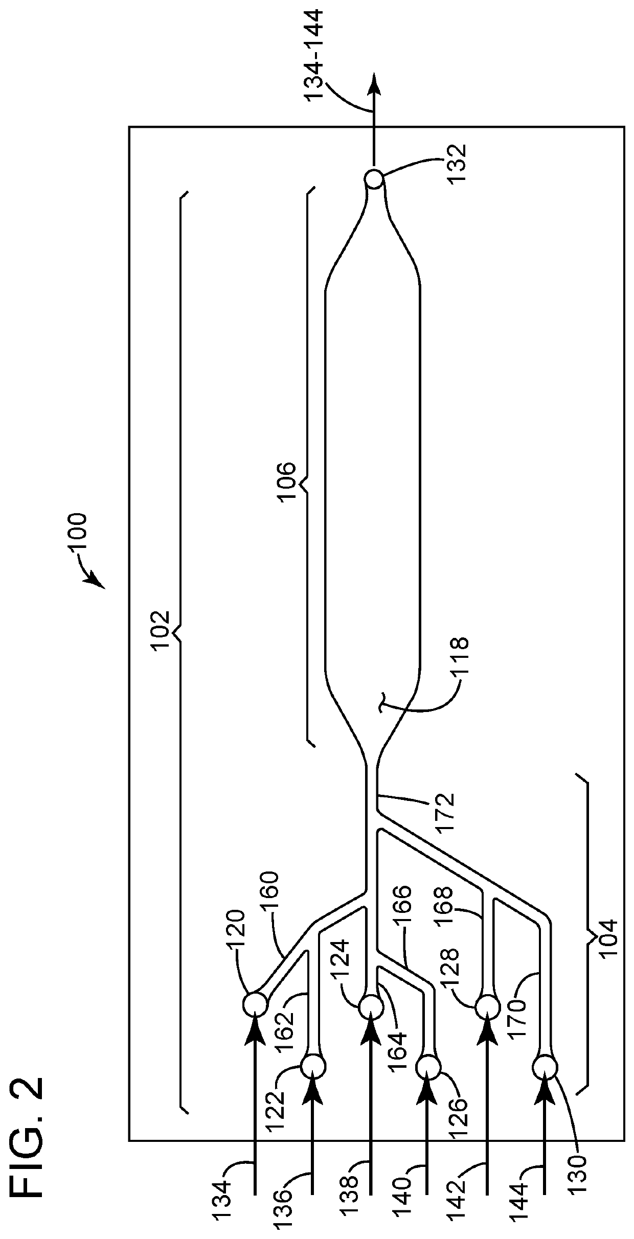
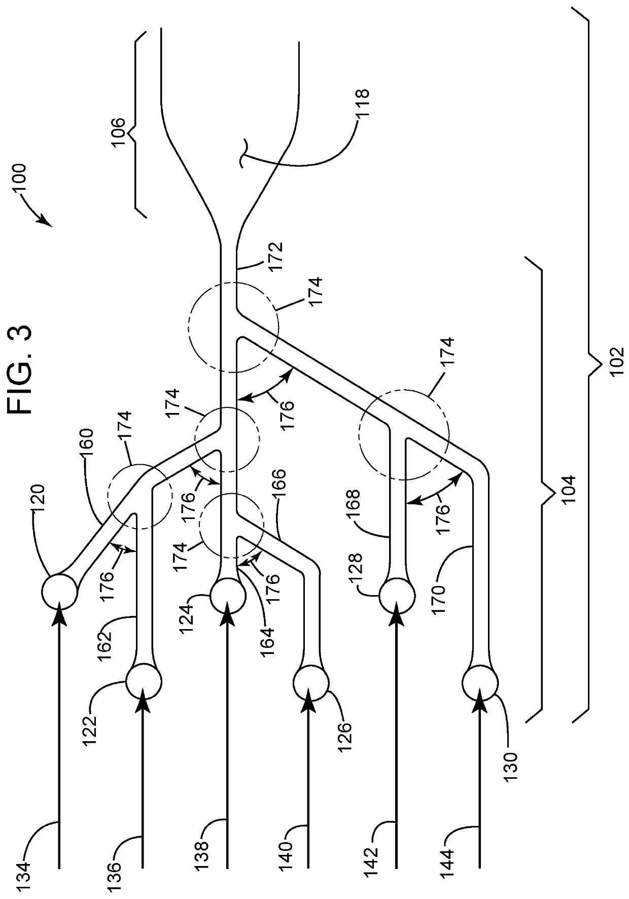
[0009]The present disclosure provides examples wherein the manifold section is small relative to the detection section to reduce the total flush volume used to achieve a certain flush efficiency. The present disclosure provides examples wherein the manifold section and detection section are in the same plane, or planar, to help reduce dead areas of reagent flow. Further the present disclosure provides examples of the manifold section having reagent flow path junctions formed solely at acute angles to also help reduce dead areas of reagent flow.

Problems solved by technology

However, reagents utilized in such sequenced chemical reactions may be very expensive.
Dead areas may be areas of slow moving laminar flow, eddies or vortices that can trap reagent and make it difficult to flush the reagent out.
These dead areas in some instances may require a significant amount of flushing reagent volume to flush out a previously positioned reagent that remains after a previous chemical reaction (e.g., a remaining reagent) caught in those dead areas.

Method used


Image

  • Flow cell with integrated manifold
  • Flow cell with integrated manifold
  • Flow cell with integrated manifold

Examples


Embodiment Construction

[0022]Certain examples will now be described to provide an overall understanding of the principles of the structure, function, manufacture, and use of the methods, systems, and devices disclosed herein. One or more examples are illustrated in the accompanying drawings. Those skilled in the art will understand that the methods, systems, and devices specifically described herein and illustrated in the accompanying drawings are non-limiting examples and that the scope of the present disclosure is defined solely by the claims. The features illustrated or described in connection with one example may be combined with the features of other examples. Such modifications and variations are intended to be included within the scope of the present disclosure.

[0023]The terms “substantially”, “approximately”, “about”, “relatively,” or other such similar terms that may be used throughout this disclosure, including the claims, are used to describe and account for small fluctuations, such as due to v...


PUM

PropertyMeasurementUnit
gap heightaaaaaaaaaa

Abstract

In one example, a flow cell includes a plurality of inlet ports sized to receive a flow of reagent from one of a plurality of reagents into the flow cell. An outlet port of the flow cell is sized to pass each flow of reagent out of the flow cell. A flow channel of the flow cell is positioned between, and in fluid communication with, each inlet port and the outlet port. The flow channel includes a manifold section and a detection section. The manifold section has a plurality of manifold branches in fluid communication with a common line, wherein each branch is connected to one of each inlet port. The detection section is in fluid communication with the common line and the outlet port. The detection section is operable to perform a plurality of different chemical reactions between the plurality of reagents and analytes positioned in the detection section.

Description

CROSS-REFERENCE TO RELATED APPLICATIONS[0001]This application is a non-provisional of, and claims the benefit of the filing date of, U.S. provisional application 62 / 666,897, filed May 4, 2018, entitled, “Flow Cell with Integrated Manifold,” the contents of which are incorporated herein by reference.BACKGROUND[0002]Many instruments that use microfluidic devices may include a plurality of reagent wells that contain a variety of reagents, wherein each reagent well is connected to a rotary selector valve. The rotary valve aligns with each well channel in order to select any one of the reagents. A common line is then utilized to route the selected reagents from the rotary valve to an inlet port of a flow cell. Analytes, such as DNA segments, nucleic-acid chains or the like, may be positioned in the flow channel. The selected reagents may flow through the flow cell in order to perform various controlled chemical reactions on the analytes.[0003]In order to minimize, and in some instances e...

Claims


Application Information

Patent Timeline
Patent Type & Authority Applications(United States)
IPC IPC(8): B01L3/00G01N21/05
CPCB01L2400/08B01L3/502707B01L3/502715B01L3/502738B01L2300/0861G01N21/05B01L2400/0622G01N33/00B01L2200/026B01L2300/0816B01L2300/0867B01L2400/0487B01L2400/049B01L2400/0655
Inventor LIN, SZ-CHINTAYLOR, JAYRHEE, MINSOUNGFOLEY, JENNIFERCOX-MURANAMI, WESLEYDELATTRE, CYRILKHURANA, TARUNCRIVELLI, PAUL
Owner ILLUMINA INC
Why Eureka
Try Eureka