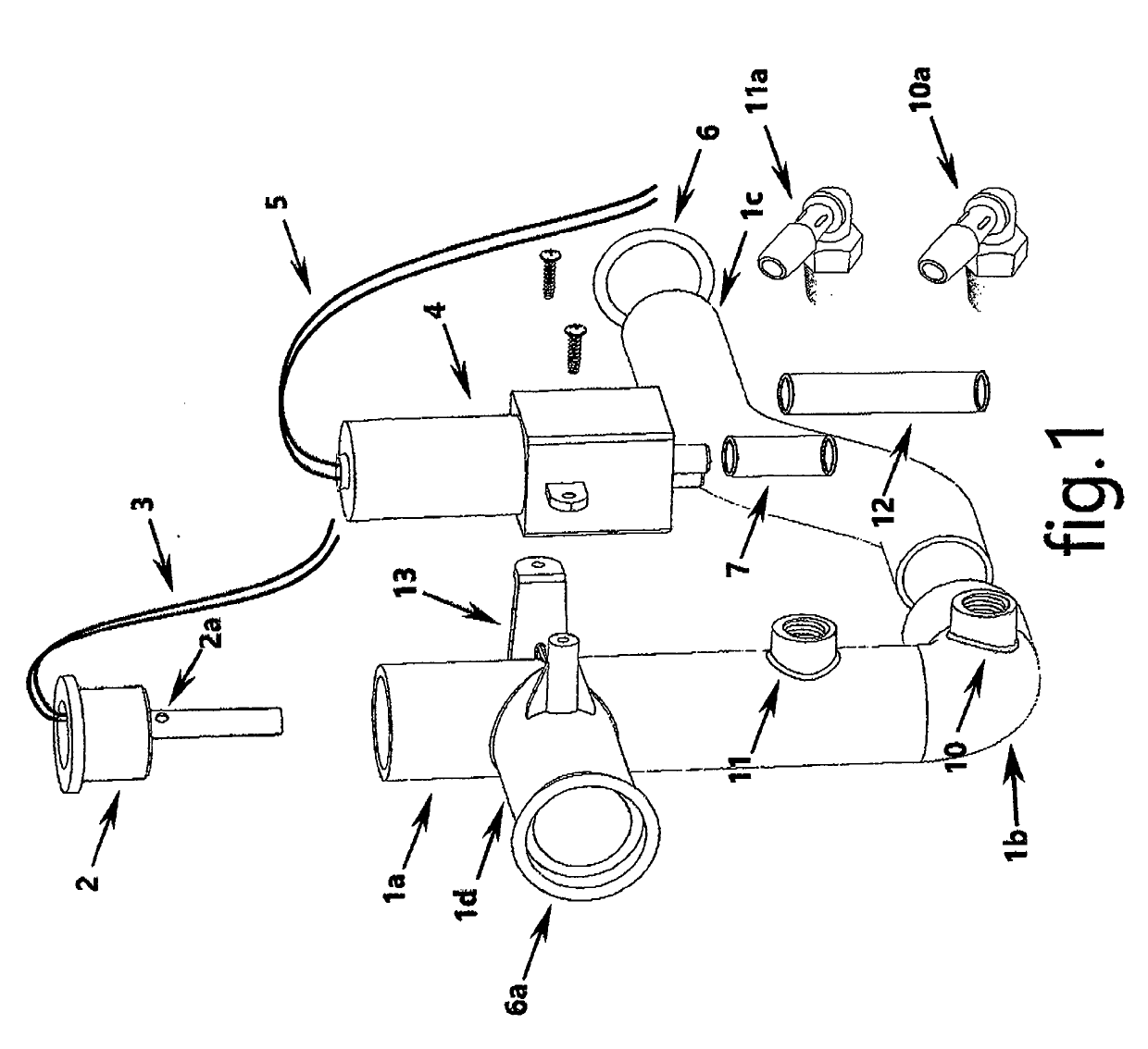
The present invention comprises a self-cleaning condensate drain
fluid pressure trap for
air conditioning.
Particulates present in the air which pass through an air conditioner adhere to moister (condensation) which is present on the internal
evaporator coil. Condensation drips off the
evaporator coil along with the
particulates which has mixed in with it. Air-conditioning condensate fluid and
particulates, or debris, accumulate inside an air-conditioner
evaporator coil drain pan and are drained outward through the condensate fluid drain opening. Condensate
fluid pressure traps, necessary accessories of a condensate drain line, are normally secured to the drain pan right outside of the air conditioners drain opening. Since condensate fluid is slow flowing, and not pressurized, debris that drains out of the air conditioner tends to settle in the bottom of the condensate
fluid pressure trap. The debris will build up until a clog or restriction to
drainage flow occurs. This description of events is based on my experience as an
HVAC service
technician and from cases gathered from other
HVAC professionals.This device, a self-cleaning condensate drain pressure trap for
air conditioning, can prevent
air conditioning condensate drain pan fluid overflows due to debris restrictions which occur in the condensate drain fluid pressure trap or elsewhere in the condensate drain line. In preferred embodiments a
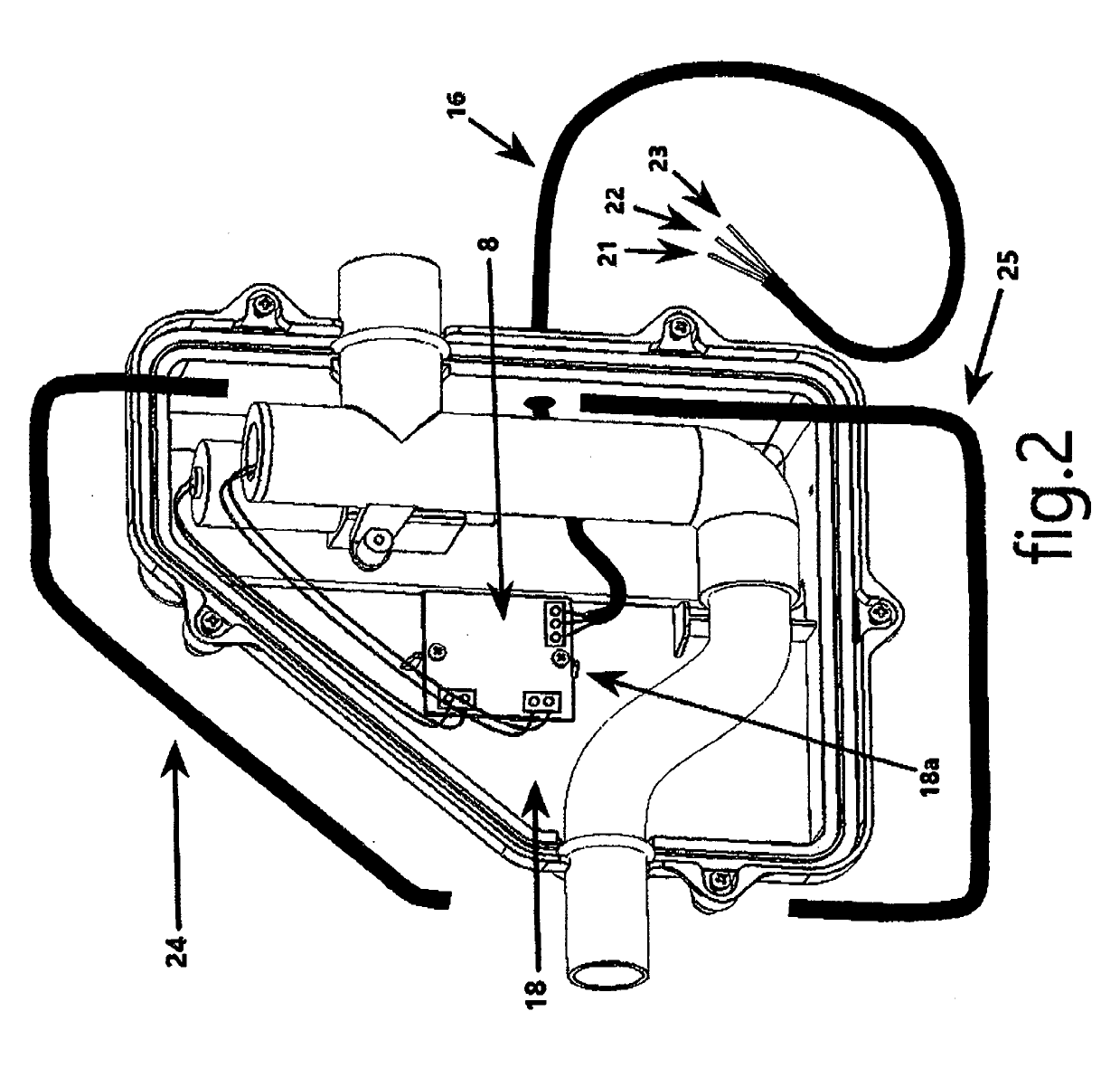
printed circuit board (PCB) is an incorporated part in the self-cleaning condensate drain pressure trap
assembly. The PCB is designed to sense condensate fluid in the sensor cap at the high level of section 1a of the fluid pressure trap. Once the positive presence of fluid is sensed a
relay on the PCB breaks the control
voltage to the air-conditioners controls or
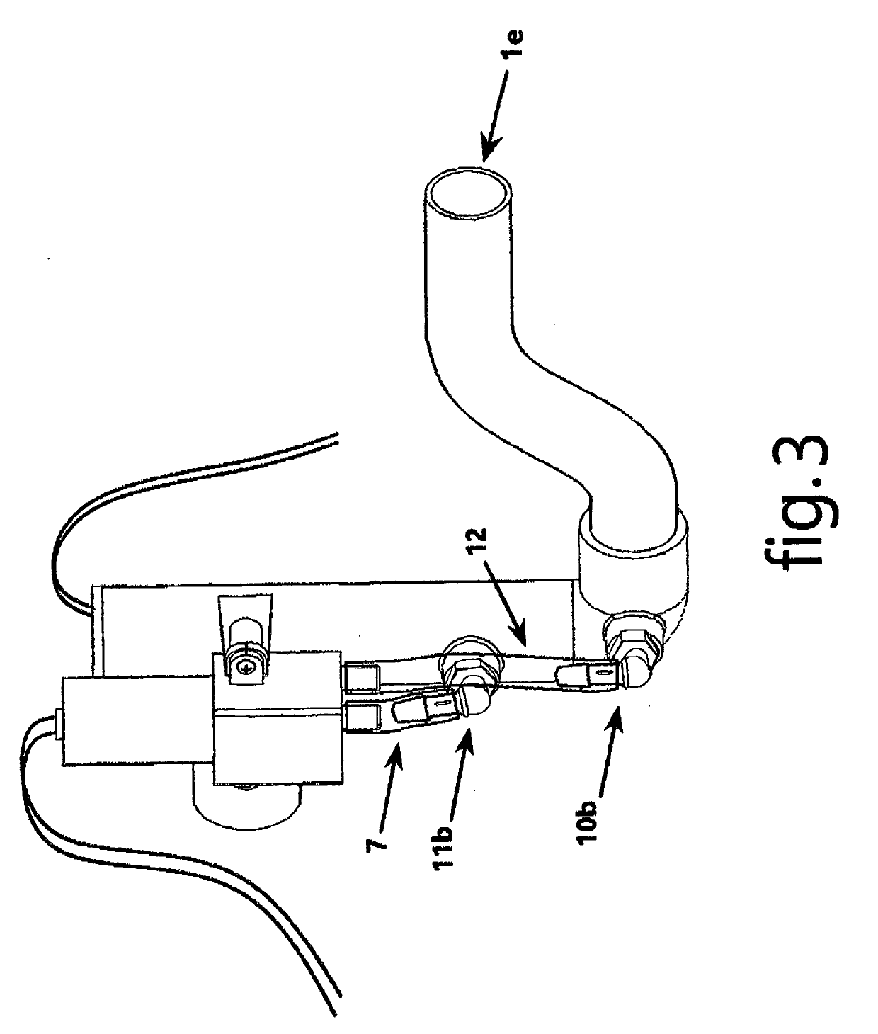
thermostat. The invention then utilizes the incorporated fluid pump to circulate condensate drain fluid from section 1a of the pressure trap into section 1b of the pressure trap in a manner which is perpendicular to the
normal fluid drainage flow through the fluid trap. This fluid pumping action loosens debris in section 1b and allows the drain fluid accumulated in the drain pan of the A / C unit to push the debris restriction out of the pressure trap by kinetic gravitational fluid force. After the debris is broken down and pushed through the fluid trap condensate drainage will resume. Unless there is another fluid restriction elsewhere in the drain line. When the PCB senses a negative presence of fluid at the sensor cap air-conditioner operations will be restored. If fluid drainage restrictions persist and a positive fluid presence at the sensor cap continues the PCB will continue to prevent the air conditioners operations. This will halt further production of condensate fluid to prevent condensate drain pan fluid overflow.The (self-cleaning condensate drain pressure trap) is not intended to remedy all causes of condensate fluid drainage restriction. Nor is it designed to clean out the entire condensate drain line. The varied reasons for this this are listed in the ‘background of the invention’ section of this application. In short, problems that occur within condensate fluid drain lines are too varied in nature and the construction methods of said drain lines are vast as well. In my professional opinion, any attempt to solve all relative drainage issues with a single device is not practical. That is why this device merely intends to resolve condensate fluid drainage issues which occur due to the restriction of the condensate fluid through the condensate fluid pressure trap.A device like (The self-cleaning condensate drain pressure trap) has been designed for the purpose of cleaning out entire condensate drain lines. The related patent (U.S. PG-Pub 2014 / 0130529), is flawed in certain embodiments where it is to be used. The device requires additional fluid
trapping and / or elaborate external
piping for it to function as a cleaning tool. It will experience failure(s) and / or cause damages when applied in condensate drain lines where more than one air conditioners share a
common drain line or where drain line sections are not properly secured. The reasoning for these failures is laid out in the ‘background of the invention’ part of this application, sections (0004 thru 0007). These observations are based on my professional
HVAC experience and the conclusions gathered by interview of other HVAC professionals.Another patent (U.S. PG-PUB 2005 / 0138939) is shown to incorporate a fluid sensor, actuated by ‘
electrode’. The patent in not unlike the engineered function of the PCB's fluid sensing ability described herein the (self-cleaning condensate drain pressure trap for air conditioning). However, it is laid out in the ‘background of the invention’ part of this application section (0012 & 0013) why the patent (U.S. PG-PUB 2005 / 0138939) is flawed in its design and is prone to failure. In short, the electrodes described therein are unshielded or unprotected from the
moisture rich environment in which they are applied. This will cause failure of the device in a variety of manners from short
cycling of the control systems to simple failure due to
corrosion and / or retarded
conductivity of the electrodes by surface
contamination. The improved designs made herein the (self-cleaning condensate pressure trap for air-conditioning) are a method for fluid detection in condensate systems which functions in a superior manner. This method is a replacement to the use of fluid float controls and has been manufactured and tested to function in a superior manner as a fluid sensor. The sensor cap of (The self-cleaning condensate pressure trap for air-conditioning) is a fluid splash-guard for the wires, which are contained therein, that convey the presence of fluid to the PCB. The wires have a plastic
coating as well to protect them from surface
contamination. The sensor cap and wire designs were engineered after observations while testing fluid sensing models determined that these elements were required to ensure proper operation. These elements also enable the fluid sensing capabilities to continue in a prolonged state of usage in a
moisture rich environment.Finally, the
engineering of the device (
self cleaning condensate drain pressure trap for air conditioning) was kept as ergonomic as possible with as little parts as were necessary to perform the functions listed herein. In particular embodiments the device is constructed with materials that allow it to be used in indoor as well outdoor application. The device is resistant to U.V. rays, high ambient temperatures, debris and
moisture. The device is light weight and can be supported merely by connection to the condensate drain line. The Installation method of (
self cleaning condensate drain pressure trap for air conditioning) is the same as standard condensate fluid pressure traps, apart from the control wiring which must be connected to the air conditioner for cleaning and safety functions. Although, the device will function as a condensate fluid pressure trap whether power is applied or not.

