Pressure activated metallic band piston seal

a technology of metallic band and piston, which is applied in the direction of sealing, sealing, transportation and packaging, etc., can solve the problems of leakage gap between the piston and the tensioner body, and achieve the effect of reducing leakag

Inactive Publication Date: 2019-11-07
BORGWARNER INC
View PDF0 Cites 1 Cited by
  • Summary
  • Abstract
  • Description
  • Claims
  • Application Information

AI Technical Summary

Benefits of technology

[0006]In another embodiment, a method of reducing leakage between a piston and a tensioner body in a hydraulic tensioner comprising a tensioner body having a bore in fluid communication with a source of pressurized fluid through an inlet, a hollow piston slidably received within the bore and having an outer diameter, a hydraulic pressure chamber defined by the hollow piston and the bore of the tensioner body, a piston spring received within the hydraulic pressure chamber for biasing the piston away from the inlet, and a metallic band surrounding the outer diameter of the piston, comprises the step of activating the band to create a seal between the piston and the tensioner body such that the seal reduces leakage of oil from the hydraulic pressure chamber.

Problems solved by technology

A leakage gap exists between the piston and the tensioner body of hydraulic tensioners.

Method used


Image

  • Pressure activated metallic band piston seal
  • Pressure activated metallic band piston seal
  • Pressure activated metallic band piston seal

Examples


first embodiment

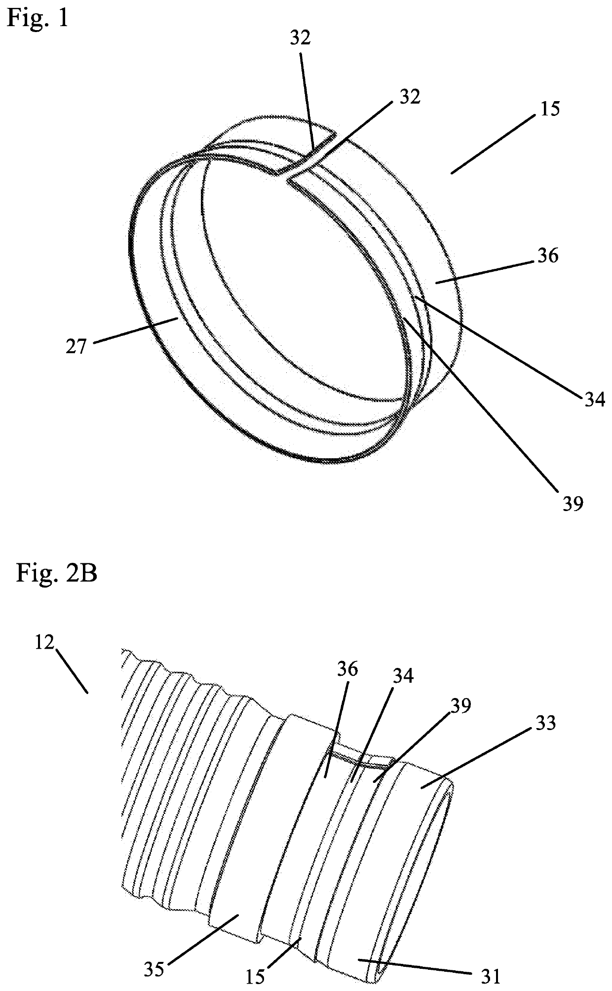
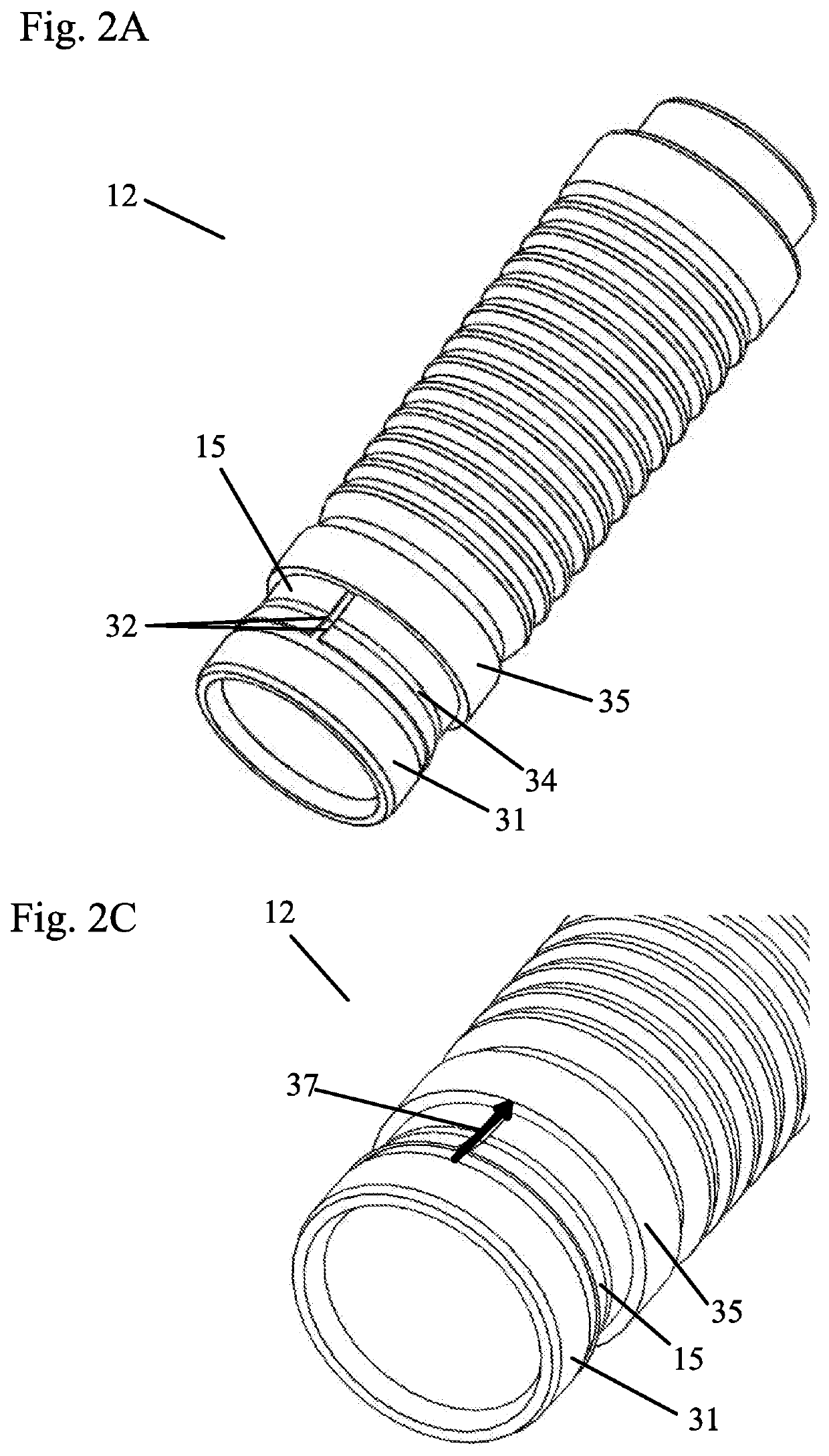
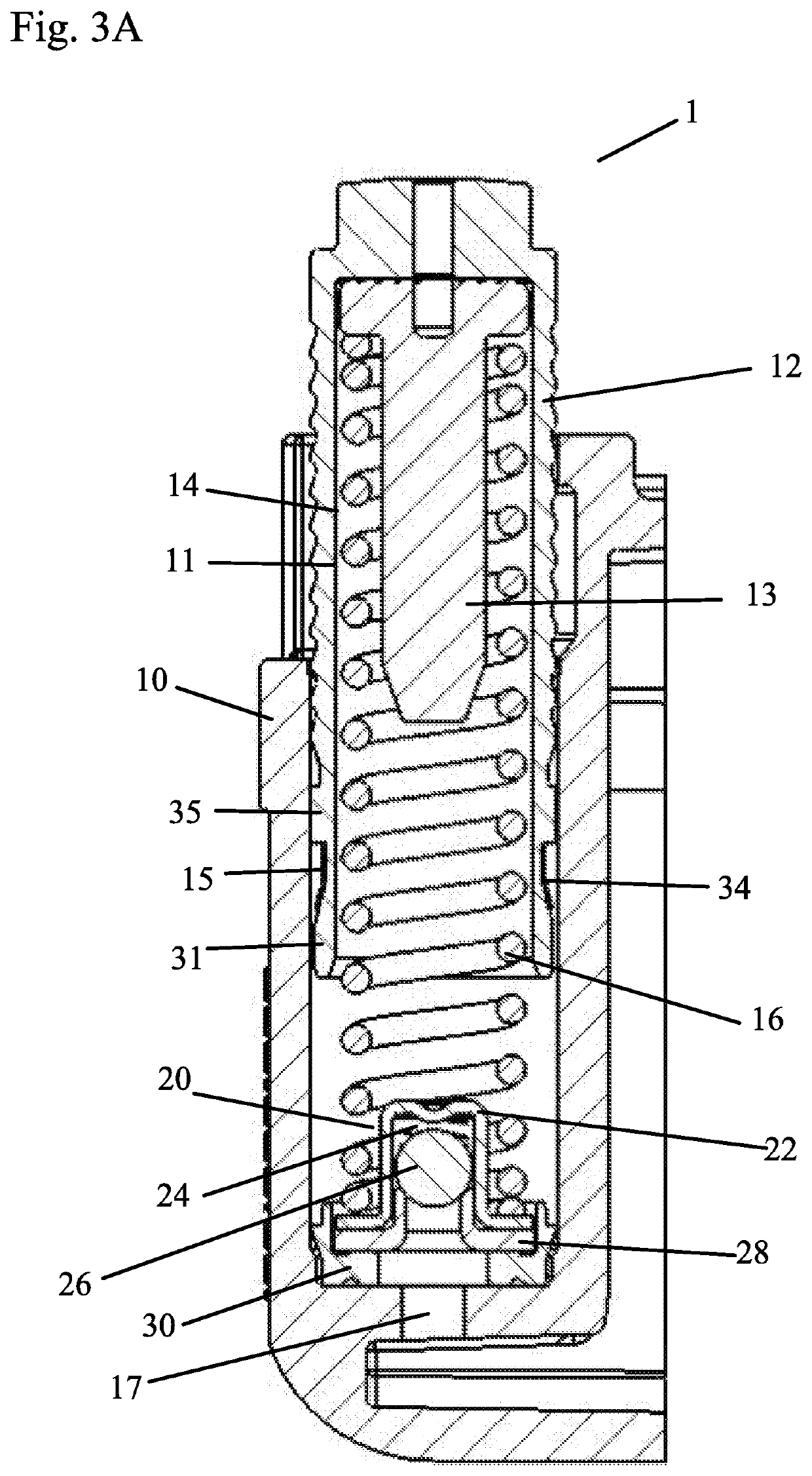
[0047]FIGS. 1-5B show a tensioner 1 with a metallic band, which is a bent seal 15 in this embodiment. The tensioner 1 includes a tensioner body 10, a piston 12, a vent disk 13 (to reduce volume of the tensioner), a hydraulic pressure chamber 14, a check valve assembly 20, a piston seal 15, and a spring 16. The tensioner body 10 defines a cylindrical bore 11 for slidably receiving the hollow piston 12. One end of the bore 11 contains an inlet 17 in fluid communication with an external supply of pressurized fluid (not shown). The hydraulic pressure chamber 14 is defined by an inner circumference of the hollow piston 12, bore 11, compression spring 16 and the check valve assembly 20. The compression spring 16 biases the piston 12 away from the inlet 17. The check valve assembly 20 is located at the base of the piston bore 11 to allow hydraulic fluid to fill the space in the piston bore 11. Although any check valve assembly known in the art could be used, the check valve assembly 20 in ...

second embodiment

[0049]FIGS. 6-10B show a tensioner 2 with a metallic band, which is a flat floating seal 45 in this embodiment. The tensioner 2 includes a tensioner body 40, a piston 42, a vent disk 43 (to reduce volume of the tensioner), a hydraulic pressure chamber 44, a check valve assembly 50, a piston seal 45, and a spring 46. The tensioner body 40 defines a cylindrical bore 41 for slidably receiving the hollow piston 42. One end of the bore 41 contains an inlet 47 in fluid communication with an external supply of pressurized fluid (not shown). The hydraulic pressure chamber 44 is defined by an inner circumference of the hollow piston 42, bore 41, compression spring 46 and the check valve assembly 50. The compression spring 46 biases the piston 42 away from the inlet 47. The check valve assembly 50 is located at the base of the piston bore 41 to allow hydraulic fluid to fill the space in the piston bore 41. Although any check valve assembly known in the art could be used, the check valve assem...

third embodiment

[0051]FIGS. 11-15B show a tensioner 3 with a metallic band, which is a flat seal 75 in this embodiment. The band 75 in FIGS. 11-15B is similar to the band 45 in FIGS. 6-10B, however, the band 75 in FIGS. 11-15B is sized to be tightly fit around the piston 72, while the band 45 in FIGS. 6-10B is sized to be loosely fit around the piston. As a result, the pressure acts on the bands in FIGS. 11-15B differently than the bands in FIGS. 6-10B. In FIGS. 6-10B, there is a cavity formed between the band and the piston surface and, in FIGS. 11-15B, cross holes create a path for high pressure oil to act directly on the underside of the band.

[0052]The tensioner 3 includes a tensioner body 70, a piston 72, a vent disk 73 (to reduce volume of the tensioner), a hydraulic pressure chamber 74, a check valve assembly 80, a piston seal 75, and a spring 76. The tensioner body 70 defines a cylindrical bore 71 for slidably receiving the hollow piston 72. One end of the bore 71 contains an inlet 77 in flu...


PUM


Abstract

This invention pertains to the field of hydraulic tensioners. A hydraulic tensioner of this invention includes a tensioner body having a bore in fluid communication with a source of pressurized fluid through an inlet, a hollow piston slidably received within the bore and having an outer diameter, a hydraulic pressure chamber defined by the hollow piston and the bore of the tensioner body, a piston spring received within the hydraulic pressure chamber for biasing the piston away from the inlet, and a metallic band surrounding the outer diameter of the piston. The metallic band forms a seal between an outer surface of the piston and the tensioner body when pressure builds in the hydraulic pressure chamber, wherein metallic bands or seals are placed over a hydraulic tensioner piston in order to seal the high pressure chamber and prevent or reduce leakage through the clearance between the piston and the tensioner body.

Description

BACKGROUND OF THE INVENTIONField of the Invention[0001]The invention pertains to the field of hydraulic tensioners. More particularly, the invention pertains to metallic seals for pistons.Description of Related Art[0002]A leakage gap exists between the piston and the tensioner body of hydraulic tensioners.SUMMARY OF THE INVENTION[0003]A metallic band that is either spiral or circularly wound is placed over a hydraulic tensioner piston in order to seal the hydraulic pressure chamber and prevent or reduce leakage through a clearance between the piston and the tensioner body.[0004]In one embodiment, a hydraulic tensioner includes a tensioner body having a bore in fluid communication with a source of pressurized fluid through an inlet, a hollow piston slidably received within the bore and having an outer diameter, a hydraulic pressure chamber defined by the hollow piston and the bore of the tensioner body, a piston spring received within the hydraulic pressure chamber for biasing the pi...

Claims


Application Information

Patent Timeline
Patent Type & Authority Applications(United States)
IPC IPC(8): F16H7/08F16J9/08
CPCF16H2007/0806F16H2007/0859F16H7/0848F16H2007/0851F16J9/08F16H2007/0812F16H7/0834F16H7/08F16H7/0836F16J15/28Y10S277/939F16J15/00
Inventor BENN, JEREMYHONG, SEONGDO
Owner BORGWARNER INC
Why Eureka
Try Eureka