Gas appliance and control method thereof

a technology of gas appliances and control methods, applied in the field of gas appliances, can solve problems affecting security, achieve the effects of improving security of gas appliances, reducing ignition time and power consumption, and speeding up the ignition procedure with the ignitor

Active Publication Date: 2019-11-07
GRAND MATE
View PDF14 Cites 2 Cited by
  • Summary
  • Abstract
  • Description
  • Claims
  • Application Information

AI Technical Summary

Benefits of technology

[0013]The advantage of the present invention is that through defining the sensing voltage output from the thermocouple as the first voltage for identifying the successful ignition, the ignition procedure with the ignitor could be speeded up, and the ignition time and the power consumption during the ignition could be reduced. The gas could further be blocked earlier as the second voltage, which is higher than the first voltage, is utilized for identifying the extinguished flames, thereby improving the security of the gas appliance.
[0014]The present invention will be best

Problems solved by technology

However, the user could not identify whether the electromagnetic valve has the constant magnetic field or not, and could only identify rely on his experience, resulting in inconvenience.
In this way, when the flames are extinguished with a large

Method used


Image

  • Gas appliance and control method thereof
  • Gas appliance and control method thereof
  • Gas appliance and control method thereof

Examples


first embodiment

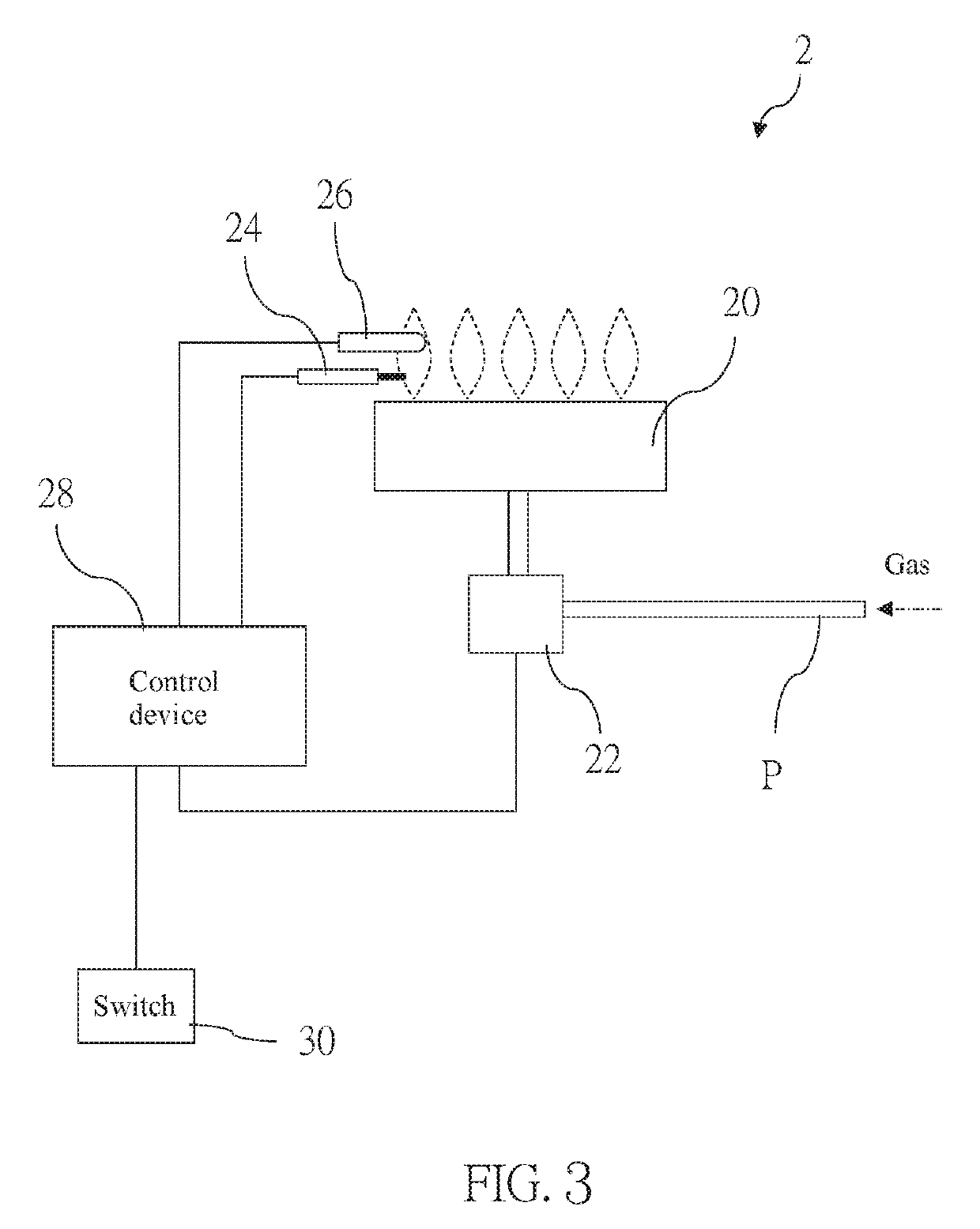
[0020]The following illustrative embodiments and drawings are provided to illustrate the disclosure of the present invention, these and other advantages and effects can be clearly understood by persons skilled in the art after reading the disclosure of this specification. As shown in FIG. 3, a gas appliance 2 of a first embodiment according to the present invention includes a burner 20, a gas valve 22, an ignitor 24, a thermocouple 26, and a control device 28. In this embodiment, the gas appliance 2 is a gas stove as an example. However, this is not a limitation of the present invention. The gas appliance 2 could also be a gas heating device such as a fireplace or a water heater for example.

[0021]The burner 20 includes at least one flame port which is adapted to burn gas to generate flames. The gas valve 22 is disposed on a gas pipe P communicating with the burner 20. The gas valve 22 is controllable to open or block the gas pipe P and regulate a gas flow supplying to the burner 20....

second embodiment

[0030]Sometimes the flames are blew by wind and lose contact with the thermocouple 26 temporarily but soon contact with the thermocouple 26 again, which makes the sensing voltage output from the thermocouple 26 become lower than the second voltage V2 in a short time but then become higher than the second voltage V2 again. Hence, the control device 28 would identify that the flames are extinguished and control the gas valve 22 to block the gas pipe P. In order to prevent the aforementioned situation, in a second embodiment, it could further include a step of controlling the gas valve 22 to block the gas pipe P until the sensing voltage is continuously lower than the second voltage V2 for a predetermined period of time such that the gas would not be blocked as the flames lose contact with the thermocouple 26 temporarily. Preferably, the predetermined period of time is within ten seconds, that is, the gas valve 22 is controllable to block the gas pipe P within ten seconds after the tim...

third embodiment

[0031]After step S04, a control method for the gas appliance 2 of a third embodiment further includes the following steps. The control device 28 is adapted to identify the gas flow rate, which is regulated by the gas valve 22, supplying to the burner 20 (e.g., the gas flow rate is identified according to an opening degree of the gas valve 22 or is identified by utilizing an anemometer). When the gas flow rate supplying to the burner 20 reaches a predetermined gas flow rate for a predetermined period of time (e.g., two to five minutes in this embodiment), or when a slope of the sensing voltage with respect to time decreases to a predetermined slope (that is, a temperature of the flames is stable), a voltage of the sensing voltage would be recorded and a new first voltage V1 for next ignition would be set based on the recorded voltage. The aforementioned predetermined slope is larger than or equal to zero. In this embodiment, the recorded voltage is at least divided by two to be set a...


PUM


Abstract

A gas appliance includes a burner, a gas valve, an ignitor, a thermocouple, and a control device, wherein the control device is adapted to execute a control method comprising the following steps: controlling the ignitor to ignite and the gas valve to open; receiving a sensing voltage output from the thermocouple; stop the ignitor from igniting and controlling the gas valve to keep a gas pipe be in an open state when the sensing voltage increases to a first voltage; receiving the sensing voltage output from the thermocouple continuously, and controlling the gas valve to block the gas pipe when the sensing voltage decreases from higher than a second voltage to lower than the second voltage, wherein the second voltage is higher than the first voltage. Whereby, an ignition procedure could be speeded up and the gas could be blocked earlier as the flames are extinguished.

Description

BACKGROUND OF THE INVENTIONTechnical Field[0001]The present invention is related to a gas appliance, and more particularly to a gas appliance which could sense flames by utilizing a thermocouple.Description of Related Art[0002]Gas appliances are usually utilized as heating devices. As comparing to electro-thermal heating devices, the gas appliances provide more heat energy by burning gas. In addition, the gas appliances also have a heating time and a response time which are faster than the electro-thermal heating devices.[0003]Referring to FIG. 1, a conventional gas appliance 1, which is a gas stove as an example, includes a burner 10, a manual gas regulating valve assembly 12, an ignitor 14, an ignition circuit 16, and a thermocouple 18. Wherein, the burner 10 is adapted to burn gas to generate flames. The manual gas regulating valve assembly 12 includes a valve body 122, a knob 124, and a switch 126, wherein the valve body 122 is disposed on a gas pipe p communicating with the bur...

Claims


Application Information

Patent Timeline
IPC IPC(8): F23N5/10F23Q9/14
CPCF23Q3/00F23N2027/36F23N2039/04F23N2035/14F23Q9/14F23N5/105F23Q3/008F23N5/242F23N5/247F23K2900/05002F23D14/725F23N5/102F23N2227/36F23N2231/06F23N2239/04F23N2235/14F24C3/103F24C3/126
Inventor HUANG, CHUNG-CHINHUANG, CHIN-YINGHUANG, HSIN-MINGHUANG, HSING-HSIUNGYEH, YEN-JEN
Owner GRAND MATE
Why Eureka
Try Eureka